Connector assembly having a noise-reducing contact pattern

a technology of contact pattern and connector, which is applied in the direction of coupling device connection, printed circuit, coupling protective earth/shielding arrangement, etc., can solve the problem that the connector does not maintain the arrangement of contacts

Active Publication Date: 2009-12-29
TYCO ELECTRONICS LOGISTICS AG (CH)
View PDF59 Cites 16 Cited by
  • Summary
  • Abstract
  • Description
  • Claims
  • Application Information

AI Technical Summary

Benefits of technology

[0004]In one embodiment, a connector assembly includes a housing and contacts. The housing extends between mating and mounting interfaces. The mating and mounting interfaces have contact openings in a noise-reducing contact pattern. The contact openings in the pattern are arranged in pairs along respective contact lines. The contact lines of adjacent pairs are transverse to one another. The contacts extend through the contact openings and are arranged in the noise-reducing contact pattern through the housing between the mating and mounting interfaces to reduce at least one of electric noise and cross-talk in signals communicated by the contacts.

Problems solved by technology

Known connectors that include the noise cancelling contact pattern described in the '807 patent do not maintain the spacing of the contacts relative to one another throughout the connector.
For example, the connectors do not maintain the arrangement of the contacts in the noise cancelling pattern throughout the connectors, or between mating and mounting ends of the connectors.

Method used


Image

  • Connector assembly having a noise-reducing contact pattern
  • Connector assembly having a noise-reducing contact pattern
  • Connector assembly having a noise-reducing contact pattern

Examples


Embodiment Construction

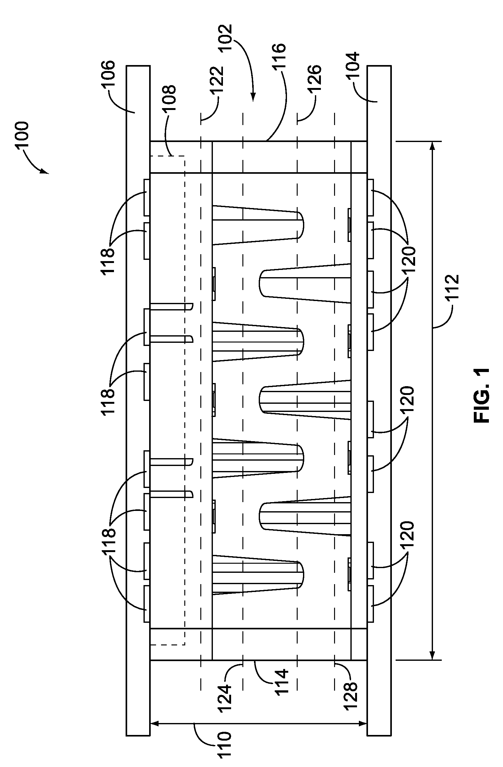
[0012]FIG. 1 is an elevational view of a mezzanine connector assembly 100 according to one embodiment. The connector assembly 100 includes a header assembly 102 that mechanically and electrically connects a plurality of substrates 104, 106 in a parallel arrangement. As shown in FIG. 1, the substrates 104, 106 are interconnected by the header assembly 102 so that the substrates 104, 106 are substantially parallel to one another. The substrates 104, 106 may include circuit boards. For example, a first or lower substrate 104 may be a motherboard and a second or upper substrate 106 may be a daughter board. The daughter board 106 includes conductive pathways 118 and the motherboard 104 includes conductive pathways 120. The conductive pathways 118, 120 communicate data signals and / or electric power between the daughter board 106 and the motherboard 104, and one or more electric components (not shown) that are electrically connected to the daughter board 106 and the motherboard 104. The co...


PUM


Abstract

A connector assembly includes a housing and contacts. The housing extends between mating and mounting interfaces. The mating and mounting interfaces have contact openings in a noise-reducing contact pattern. The contact openings in the pattern are arranged in pairs along respective contact lines. The contact lines of adjacent pairs are transverse to one another. The contacts extend through the contact openings and are arranged in the noise-reducing contact pattern through the housing between the mating and mounting interfaces to reduce at least one of electric noise and cross-talk in signals communicated by the contacts.

Description

BACKGROUND OF THE INVENTION[0001]The invention relates generally to electrical connectors and, more particularly, to a connector assembly that mechanically and electrically connects substrates.[0002]Known connectors include a differential signal contact pattern in which contacts in the connectors are arranged in a noise cancelling signal pattern. For example, U.S. Pat. No. 7,207,807 describes a noise cancelling differential connector and footprint of the contacts in the connector. The footprint, or arrangement, of the contacts reduces noise in signals communicated using the contacts. Known connectors that include the noise cancelling contact pattern described in the '807 patent do not maintain the spacing of the contacts relative to one another throughout the connector. For example, the connectors do not maintain the arrangement of the contacts in the noise cancelling pattern throughout the connectors, or between mating and mounting ends of the connectors. The connectors employ jogs...

Claims


Application Information

Patent Timeline
Patent Type & Authority Patents(United States)
IPC IPC(8): H01R13/648
CPCH01R13/502H01R12/716H01R13/4364H01R13/6471H01R13/6594Y10S439/941
Inventor TROUT, DAVID ALLISONFEDDER, JAMES LEEMCCLINTON, JEFFREY BYRON
Owner TYCO ELECTRONICS LOGISTICS AG (CH)
Why Eureka
Try Eureka