System and method for measuring electric current in a pipeline

a technology of electric current and pipeline, applied in the field of cathodic protection systems, can solve the problems of limited methods, low accuracy, and low accuracy, and achieve the effect of reducing electrical nois

Active Publication Date: 2006-09-12
SHELL USA INC
View PDF33 Cites 13 Cited by
  • Summary
  • Abstract
  • Description
  • Claims
  • Application Information

AI Technical Summary

Benefits of technology

[0012]The present invention meets the above needs and overcomes one or more deficiencies in the prior art by providing a system using a propulsion vehicle that is configured to measure a voltage differential in a current-carrying pipe. The propulsion vehicle may be outfitted with two contacts for maintaining electrical contact with the pipe as the vehicle moves through the pipe. These electrical contacts may optionally include rotating steel brushes and / or rotating steel knives. The system further includes a voltage-reading device connected to the contacts for measuring the voltage between the contacts as the vehicle moves through the pipe. A vehicle according to the present invention optionally may include electromechanical devices that reduce electrical noise.

Problems solved by technology

Such a method is limited in that only current at static locations is measured and a technician is required to visit such locations.
This technique also provides only static data and is labor intensive
Since the potential difference information must be transmitted to the measurement unit at the ground surface through the long cable connecting the downhole apparatus to the measurement unit, the information tends to be degraded due to noise pick-up and crosstalk.
In addition, thermal effects along the long cable and at the electrical connections on the surface and in the downhole tool adversely affect the information.
The electrodes utilized in this embodiment are not configured for dynamic electrical contact with the pipe, and, if such dynamic contact were attempted, the signal would be unacceptable due to noise distortion.

Method used


Image

  • System and method for measuring electric current in a pipeline
  • System and method for measuring electric current in a pipeline
  • System and method for measuring electric current in a pipeline

Examples


Embodiment Construction

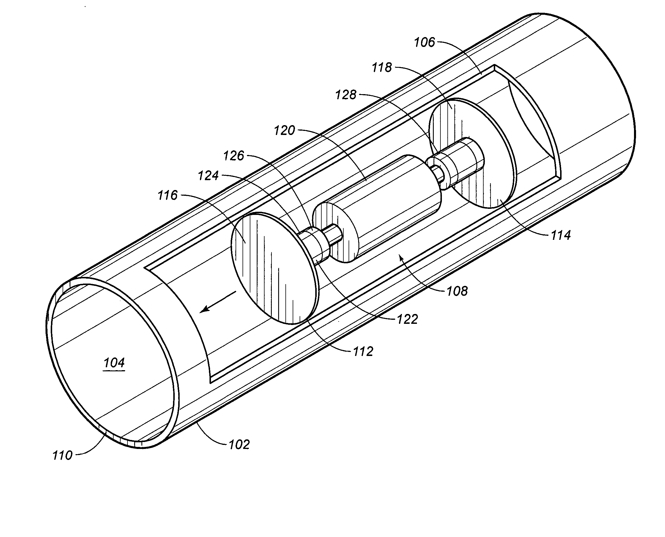
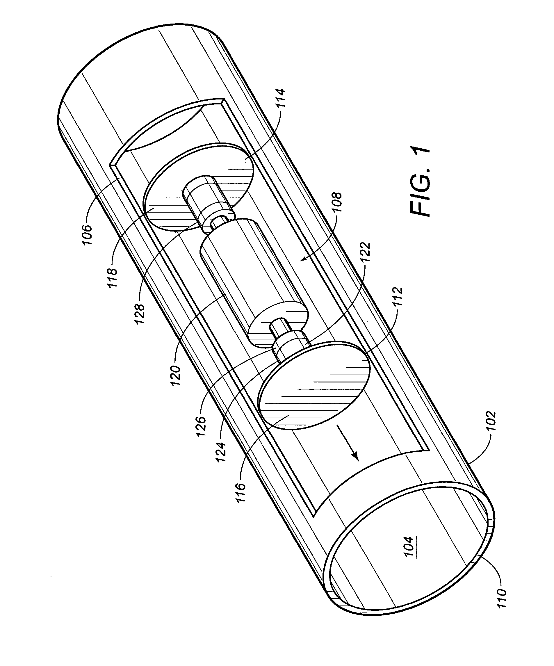
[0021]The present invention provides a system and method for measuring the electric current in a pipeline imposed by a cathodic protection system. To accomplish this, a pig is utilized.

[0022]Pigs are well known in the art and are frequently used inside pipelines to detect the presence of corrosion and other defects. Pigs may be outfitted with electronic instruments designed to inspect pipelines internally and may physically travel with a fluid product within the pipelines without simultaneously interrupting fluid flow.

[0023]Those skilled in the art will recognize a variety of techniques exist for tracking the location of a pipeline pig. In general, odometers have historically been used for distance / location tracking of pigs. Odometer technology has continued to improve over time with the incorporation of onboard electronic instrumentation. Other technologies have also been developed to track a pig's location in real-time using satellite (i.e., GPS), subsea acoustic and other techniq...


PUM

PropertyMeasurementUnit
frequencyaaaaaaaaaa
on-off voltageaaaaaaaaaa
speedaaaaaaaaaa

Abstract

A system and method for measuring a voltage differential in a current-carrying pipe using a propulsion vehicle. The system may be adapted for use with a pipeline pig or other propulsion device, which is configured to determine the electric current in a pipeline with nominal noise while the apparatus is moving. One aspect of the present invention is a pig which is outfitted with electrical contacts. These electrical contacts may optionally consist of rotating steel brushes and / or rotating steel knives. The pig includes data logging capabilities which may record location and voltage data. A pig according to the present invention optionally may include electromechanical devices which reduce electrical noise.

Description

CROSS-REFERENCE TO RELATED APPLICATIONS[0001]Not applicable.STATEMENT REGARDING FEDERALLY SPONSORED RESEARCH OR DEVELOPMENT[0002]Not applicable.TECHNICAL FIELD[0003]The present invention relates to cathodic protection systems for corrosion protection of metal objects which are buried in soil or located underwater. More particularly, the present invention relates to a system and method for measuring the electric current in a pipeline imposed by a cathodic protection system.BACKGROUND OF THE INVENTION[0004]The owners of pipelines frequently wish to monitor the status or condition of a pipeline or to check the integrity of a protection system. This may include measurement of the material type, internal diameter, and thickness of the pipe, the material type, and thickness of any internal lining if present, the presence of corrosion on the pipe, damage to the lining, the thickness of any deposits of material on the internal surface of the pipe or of the lining if present, the presence an...

Claims


Application Information

Patent Timeline
Patent Type & Authority Patents(United States)
IPC IPC(8): G01M19/00G01R19/155G01R27/08G01M99/00C23F13/04C23F13/20G01M3/00G01N17/02
CPCC23F13/04C23F13/20G01N17/02G01M3/005F16L2101/30G01N17/04F16L2201/30G01M3/00G01N17/00
Inventor POTS, BERTFAGBAYI, KOLASCOTT, P. KEVINMATEER, MARK W.
Owner SHELL USA INC
Why Eureka
Try Eureka