
Microgyroscope driving and detecting device and method based on digitization embedded system

An embedded system and detection device technology, applied in measuring devices, gyro effects for speed measurement, gyroscope/steering sensing equipment, etc., can solve the problem of inability to achieve frequency phase and amplitude stability, reduce pure analog circuit errors, and demodulate Large errors and other problems, to achieve high precision, good stability, and reduce interference

Active Publication Date: 2017-02-01
SHANGHAI JIAO TONG UNIV
View PDF5 Cites 11 Cited by
  • Summary
  • Abstract
  • Description
  • Claims
  • Application Information

AI Technical Summary

Problems solved by technology

[0005] The driving and detection circuit of the bulk acoustic wave solid wave micro-gyroscope is an important part of the gyroscope system. At present, the driving circuit of the domestic gyroscope is mostly an analog circuit, and the single-closed-loop AGC method with stable control amplitude is often used. It has large noise and cannot Defects such as self-calibration and large demodulation errors, based on the digital closed-loop circuit system can complete the frequency phase and amplitude stabilization that cannot be achieved by analog circuits, effectively reduce pure analog circuit errors, and complete system self-stabilization and demodulation of digital chip signals

Method used


Image

  • Microgyroscope driving and detecting device and method based on digitization embedded system
  • Microgyroscope driving and detecting device and method based on digitization embedded system
  • Microgyroscope driving and detecting device and method based on digitization embedded system

Examples


Embodiment Construction

[0047] The present invention will be described in detail below in conjunction with specific embodiments. The following examples will help those skilled in the art to further understand the present invention, but do not limit the present invention in any form. It should be noted that those skilled in the art can make several modifications and improvements without departing from the concept of the present invention. These all belong to the protection scope of the present invention.

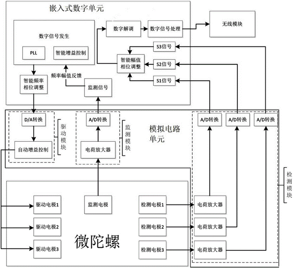
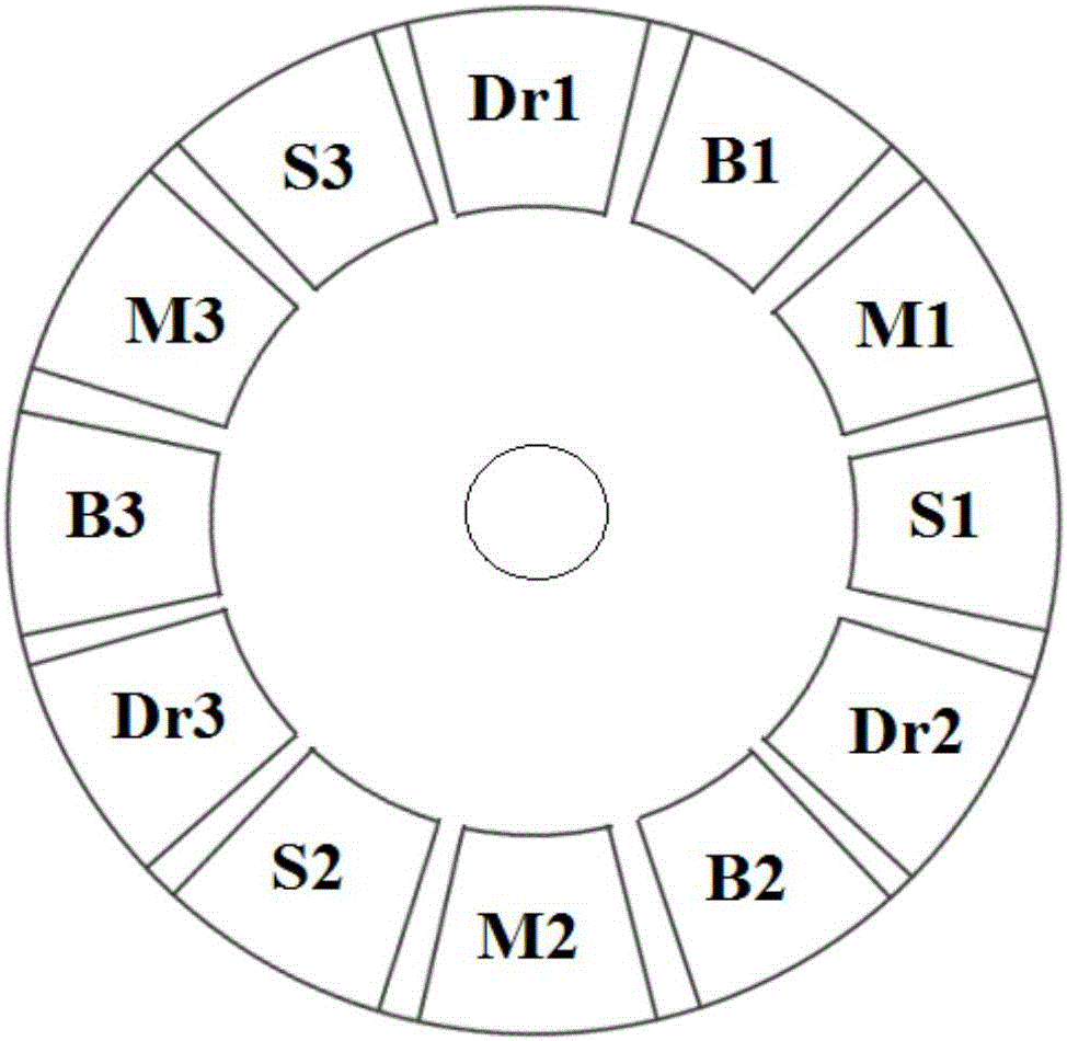
[0048] Such as figure 1 As shown, a micro-gyroscope drive and detection device based on a digital embedded system includes: an embedded digital unit, an analog circuit unit and a wireless module, and the analog circuit unit includes a drive module, a detection module and a monitoring module, and the device The working object is bulk acoustic wave solid wave micro-gyroscope; among them:

[0049] The drive module is responsible for the generation of the bulk acoustic wave solid wave micro-gyroscope...


PUM


Abstract

The invention provides a microgyroscope driving and detecting device and method based on a digitization embedded system. The device comprises an embedded data unit, a simulation circuit unit and a wireless module. The embedded data unit is connected with the simulation circuit unit, the simulation circuit unit is connected with a bulk-acoustic-wave solid fluctuation microgyroscope, and the wireless module is integrated on the embedded data unit; a driving signal is sent to the simulation circuit unit through the embedded data unit and then sent to the bulk-acoustic-wave solid fluctuation microgyroscope, a signal of the bulk-acoustic-wave solid fluctuation microgyroscope is output to the simulation circuit unit, and then is preprocessed through the simulation circuit unit and output to the embedded data unit, and signal processing is carried out; the wireless module is responsible for outputting a control instruction between the device and the outside and a final signal. By means of the microgyroscope driving and detecting device and method based on the digitization embedded system, a gyroscope signal can be effectively detected and output, the accuracy is high, and the stability is good.

Description

technical field [0001] The invention relates to the technical field of micro-electro-mechanical systems, in particular to a micro-gyro drive and detection device and method based on a digital embedded system. Background technique [0002] As a carrier angular velocity sensitive inertial sensor, the gyroscope is the core device in the inertial measurement unit (IMU), and plays a very important role in attitude control, navigation and positioning in traditional industrial fields such as aviation, aerospace, and ships. MEMS micro-gyroscopes have the advantages of small size and mass, low power consumption, low cost, good environmental adaptability, and high integration, which not only partially replace traditional gyroscopes in traditional industrial fields such as aviation, aerospace, and ships, but also can be used in the automotive industry. , industrial automation control, consumer electronics attitude stability control and other market areas are expanding at an alarming ra...

Claims


Application Information

Patent Timeline
IPC IPC(8): G01C19/5698
CPCG01C19/5698
Inventor 张卫平欧彬汪濙海唐健刘朝阳孙殿竣邢亚亮魏志方周岁寻之宇崔峰刘武
Owner SHANGHAI JIAO TONG UNIV
Learn More