Intake duct system for an engine

a technology of intake duct system and engine, which is applied in the direction of liquid degasification, auxillary pretreatment, separation process, etc., can solve the problems of deteriorating the function of foreign particle trapping, and achieve the effect of improving the function of foreign particle elimination of the intake system and preventing turbulen

Inactive Publication Date: 2009-12-29
HYUNDAI MOTOR CO LTD
View PDF10 Cites 26 Cited by
  • Summary
  • Abstract
  • Description
  • Claims
  • Application Information

AI Technical Summary

Benefits of technology

[0010]The present invention has been made in an effort to provide an intake duct system having advantages of improved functioning of foreign particle elimination.
[0011]An exemplary embodiment of the present invention provides an intake duct system for receiving air and supplying the air to an air cleaner. The exemplary intake duct system includes: a cyclone duct including a cyclone module for generating torque of the air, wherein the cyclone module includes: a central shaft; a plurality of cyclone blades that are formed outward from the central shaft; and a turbulence preventing device that is formed at a downstream side of the central shaft of the cyclone module so as to prevent turbulence of the air that has passed the cyclone blade.
[0020]According to an exemplary embodiment of the present invention, the foreign particle eliminating function of an intake system is improved by preventing turbulence at a downstream side of a cyclone module.

Problems solved by technology

In this case, the foreign particle trapping function may be deteriorated since the particles are not applied with sufficient strength of centrifugal force.

Method used


Image

  • Intake duct system for an engine
  • Intake duct system for an engine
  • Intake duct system for an engine

Examples


Embodiment Construction

[0030]Hereinafter reference will now be made in detail to various embodiments of the present invention, examples of which are illustrated in the accompanying drawings and described below. While the invention will be described in conjunction with exemplary embodiments, it will be understood that present description is not intended to limit the invention to those exemplary embodiments. On the contrary, the invention is intended to cover not only the exemplary embodiments, but also various alternatives, modifications, equivalents and other embodiments, which may be included within the spirit and scope of the invention as defined by the appended claims

[0031]An exemplary embodiment of the present invention will hereinafter be described in detail with reference to the accompanying drawings.

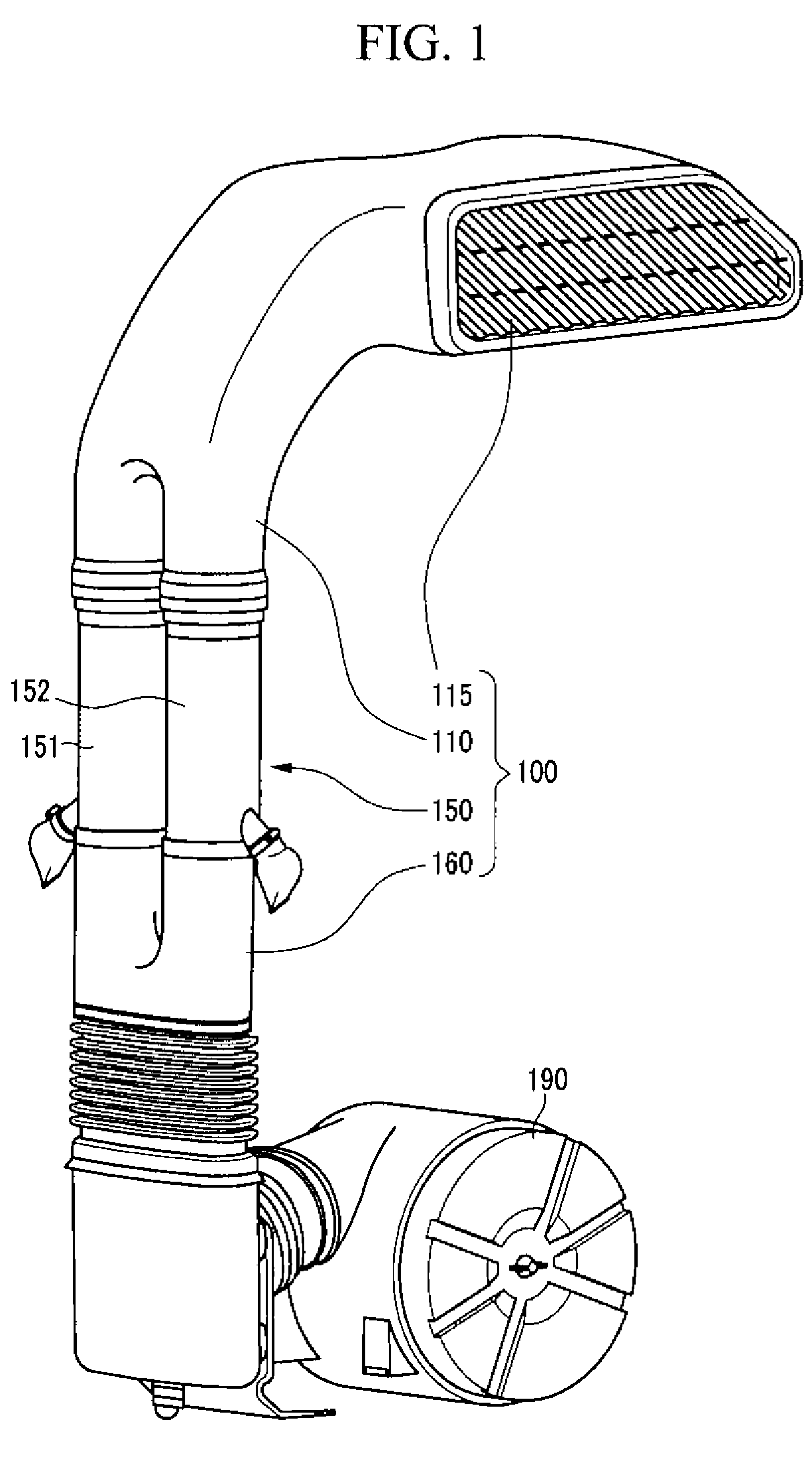
[0032]FIG. 1 is a perspective view of an intake duct system of an engine according to an exemplary embodiment of the present invention.

[0033]An intake duct system 100 for an engine according to an exemp...


PUM

PropertyMeasurementUnit
slant angleaaaaaaaaaa
longitudinal lengthaaaaaaaaaa
distanceaaaaaaaaaa

Abstract

A foreign particle eliminating function and durability of an engine may be improved by an intake duct system having a cyclone duct including a cyclone module for generating torque of air, wherein the cyclone module includes: a central shaft; a plurality of cyclone blades that are formed outward from the central shaft; and a turbulence preventing device that is formed at a downstream side of the central shaft of the cyclone module so as to prevent turbulence of the air that has passed the cyclone blade.

Description

CROSS-REFERENCE TO RELATED APPLICATION[0001]This application claims priority to and the benefit of Korean Patent Application No. 10-2007-0131647 filed in the Korean Intellectual Property Office on Dec. 14, 2007, the entire contents of which are incorporated herein by reference.BACKGROUND OF THE INVENTION[0002](a) Field of the Invention[0003]The present invention relates to an engine of a vehicle, more particularly, an intake duct system used for an engine of a vehicle.[0004](b) Description of the Related Art[0005]An internal combustion engine receives air and fuel and burns them in a combustion chamber in order to produce mechanical power. Such an engine is provided with an intake system in order to supply fresh air into the combustion chamber. In order to supply fresh air so as to increase durability of the engine, an air cleaner that purifies the air is employed.[0006]In order to improve the air purifying function of the intake system, it has been suggested to remove foreign parti...

Claims


Application Information

Patent Timeline
Patent Type & Authority Patents(United States)
IPC IPC(8): B01D45/12
CPCF02M35/022F02M35/10013F02M35/02Y02T10/146F02M35/024Y02T10/12F02B31/04F02M35/10
Inventor JUNG, SUK HWAN
Owner HYUNDAI MOTOR CO LTD
Why Eureka
Try Eureka