
Use of SCH bursts for co-channel interference measurements

a co-channel interference and burst technology, applied in the field of methods and methods, can solve the problems of co-channel interference, co-channel interference, and major limitations of cellular and pcs wireless telephone networks, and achieve the effects of improving the reliability of the system, and improving the accuracy of the measuremen

Active Publication Date: 2009-12-29
PCTEL INC
View PDF38 Cites 8 Cited by
  • Summary
  • Abstract
  • Description
  • Claims
  • Application Information

AI Technical Summary

Benefits of technology

The patent text describes a method and apparatus for identifying signal sources in multi-source signal environments, such as in cellular and PCS wireless telephone networks. The technical effect of the invention is to provide a more effective and efficient way to identify and measure the relative strength of interference from co-channel interference and adjacent-channel interference, which can be difficult in practical situations. The invention uses correlation with known patterns in the signal to achieve this goal, but there are limitations in using only fixed patterns for correlation.

Problems solved by technology

It is well known that one of the major limitations in cellular and PCS wireless telephone networks is the so-called co-channel interference.
In the case of TDMA networks, such as GSM or NADC (otherwise known as “IS-136”), co-channel interferences are often caused by the fact that the spectrum allocated to the system is reused multiple times (“frequency reuse”).
Two phenomena make such a separation difficult: co-channel interference and adjacent-channel interference.
When several base stations transmit on the same frequency, there are areas in the coverage region where conventional methods of power measurement are impractical or difficult to use when one needs to measure power from each of the interfering stations.
Under conditions where the residual error of signal estimation due to the limitations of the complexity of channel modeling exceeds the level of weaker signals (or even the weaker of the two signals) and taking into account the realistic constraints of hardware complexity, the detection of the color code is all but impossible.
Apart from poor decoding performance in practice, devices based on this approach suffer from slow scanning performance.
Although the described method apparently achieves the goal of associating interfering signal components with color codes and even with base station locations (by using RTOA-based triangulation), this technique requires complex and expensive equipment.
However, using for correlation only available fixed patterns has several drawbacks.
The problem with the pattern is that it consists of all zero bits (a piece of a CW waveform when GMSK-modulated).
This leads to a poor ability of the instrument to discern between closely-spaced (in time) signals coming from different base stations.
Another manifestation of this phenomenon is that at low signal-to-interference or signal-to-noise levels, the apparent time-of-arrival of a signal has a significant time uncertainty, displaying jitter from measurement to measurement.
Secondly, since any run of several zeros in the signal will produce a measurable output spike from the correlator, and some of these spikes will fall into the assigned time windows for detected signals, the probability of false detects cannot be too low.
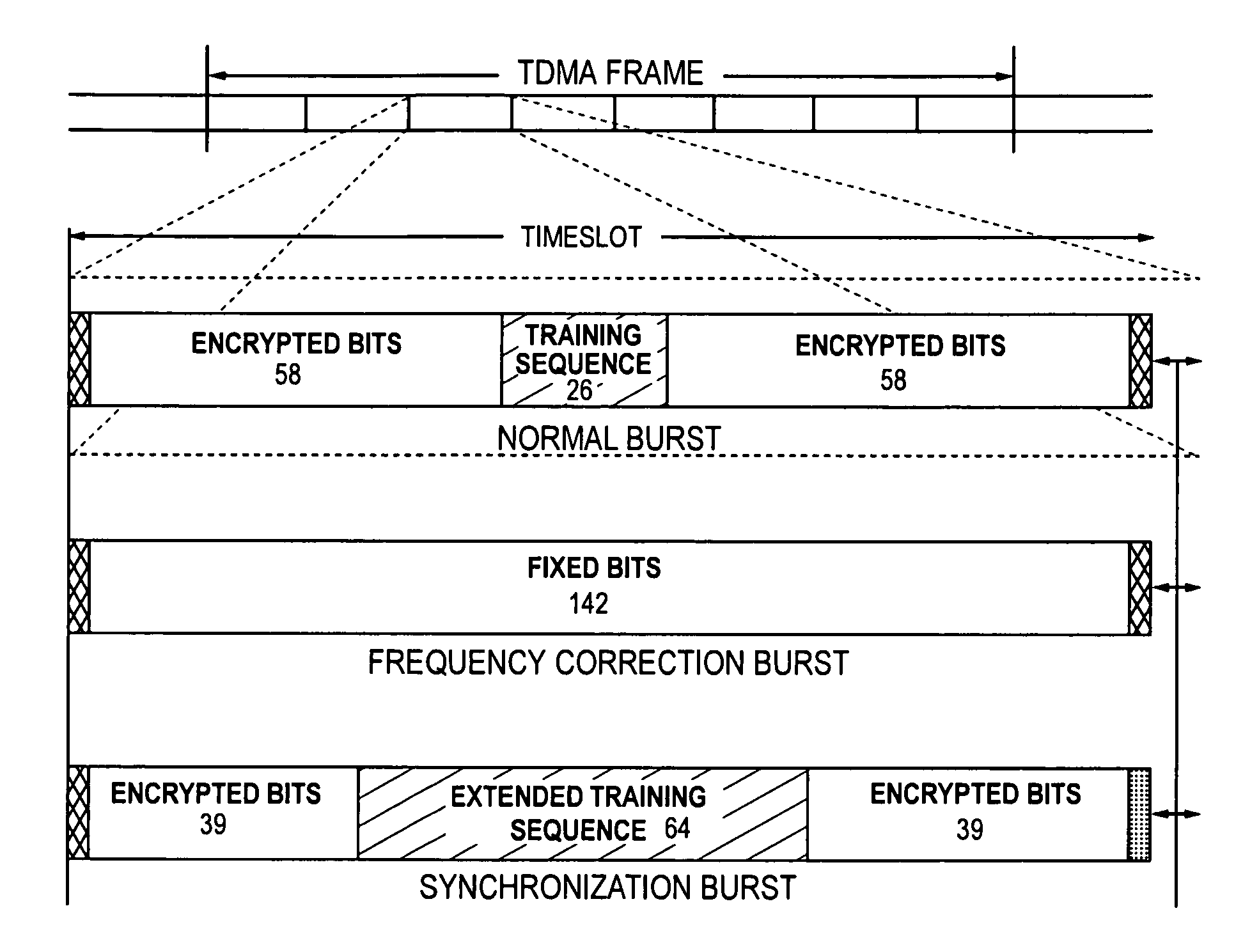
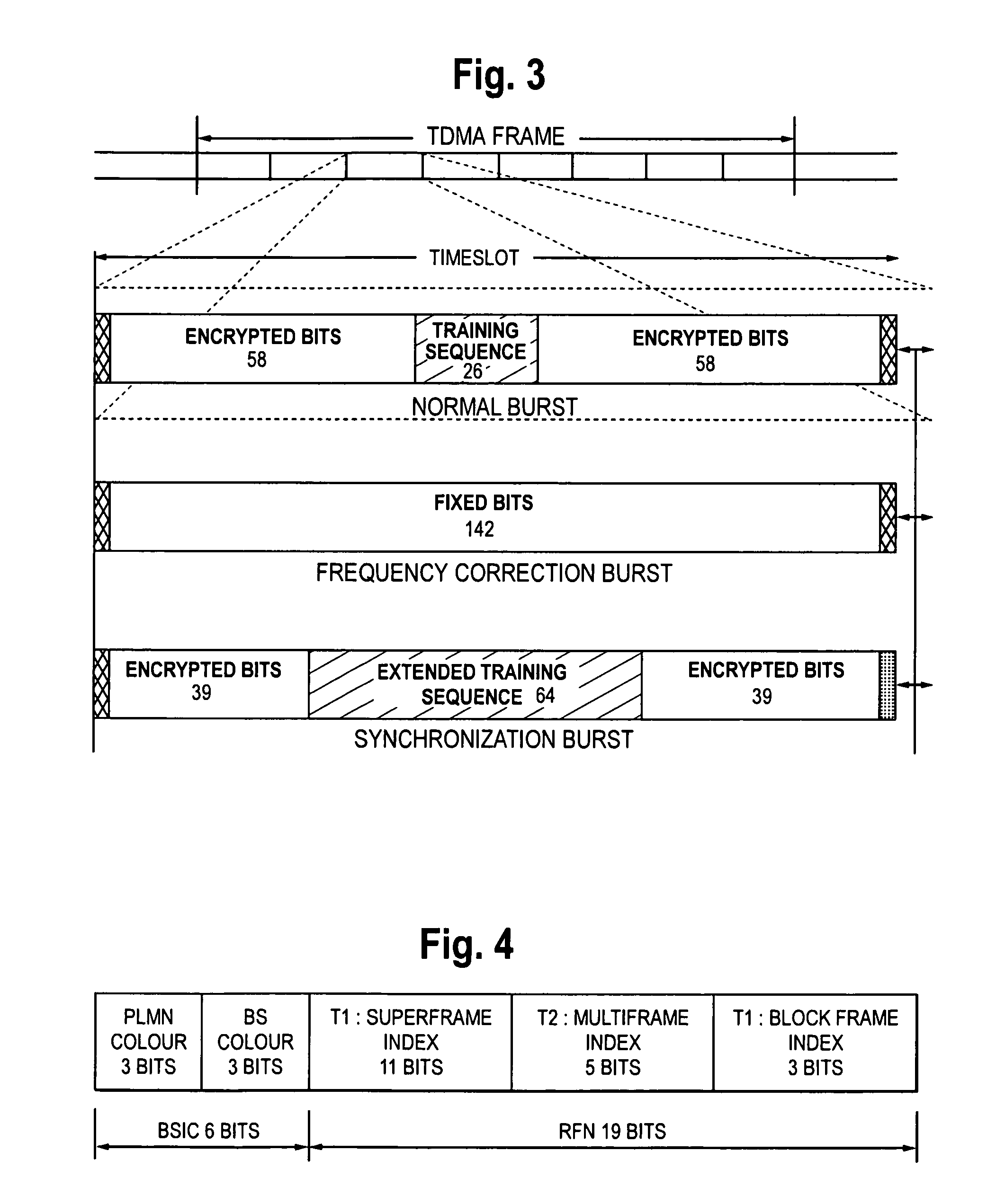
The only problem with this sequence is its relatively short length—64 symbols—that severely limits the dynamic range of the measurement.
Combining multiple copies of training sequences causes the measurement speed to slow to an unacceptable level.

Method used


Image

  • Use of SCH bursts for co-channel interference measurements
  • Use of SCH bursts for co-channel interference measurements
  • Use of SCH bursts for co-channel interference measurements

Examples


Embodiment Construction

[0024]While embodiments of this invention can take many different forms, specific embodiments thereof are shown in the drawings and will be described herein in detail with the understanding that the present disclosure is to be considered as an exemplification of the principles of the invention, as well as the best mode of practicing same, and is not intended to limit the invention to the specific embodiment illustrated.

[0025]The present invention may be embodied as a method for determining individual levels of signal components corresponding to control channels or as a device that implements the method.

[0026]Levels of signal components transmitted by each of the co-channel base stations in the area under test in a wireless network are measured and associated with the appropriate (originating) base station in presence of co-channel and adjacent-channel interference. This is done in a fully functional network without interrupting service. Embodiments of the present invention incorpora...


PUM


Abstract

A method and apparatus for identifying signal sources in a multi-source signal. Levels of signal components transmitted by each of the co-channel base stations in the area under test in a wireless network are measured and associated with the appropriate (originating) base station in the presence of co-channel and adjacent-channel interference without interrupting service by sensing and responding to received, variable, patterns.

Description

FIELD OF INVENTION[0001]The invention relates generally to the field of Time Division Multiple Access (TDMA) Cellular and Personal Communications System (PCS) networks. More particularly, the present invention relates to a method and apparatus for identifying signal sources in a multi-source signal.BACKGROUND OF THE INVENTION[0002]It is well known that one of the major limitations in cellular and PCS wireless telephone networks is the so-called co-channel interference. In the case of TDMA networks, such as GSM or NADC (otherwise known as “IS-136”), co-channel interferences are often caused by the fact that the spectrum allocated to the system is reused multiple times (“frequency reuse”). The problem may be more or less severe depending on the reuse factor, but in all cases a signal, received by a handset, will contain not only the desired forward channel from the current cell, but also signals originating in more distant cells. If the interference from a distant cell causes a degrad...

Claims


Application Information

Patent Timeline
Patent Type & Authority Patents(United States)
IPC IPC(8): H04B1/00
CPCH04B17/318H04B17/3913
Inventor DICKEY, SERGEY L.
Owner PCTEL INC
Learn More