
Adaptive wireless communication receiver

a wireless communication and receiver technology, applied in electrical equipment, digital transmission, climate sustainability, etc., can solve the problems of significant hardware area (cost) in ic design, inability to accurately measure the aci power outside the pass-band bw of the wide-band analog filter, and significant power consumption, etc., to achieve the effect of reducing power consumption, reducing power consumption, and reducing power consumption

Active Publication Date: 2012-11-15
MICROCHIP TECH INC
View PDF5 Cites 26 Cited by
  • Summary
  • Abstract
  • Description
  • Claims
  • Application Information

AI Technical Summary

Benefits of technology

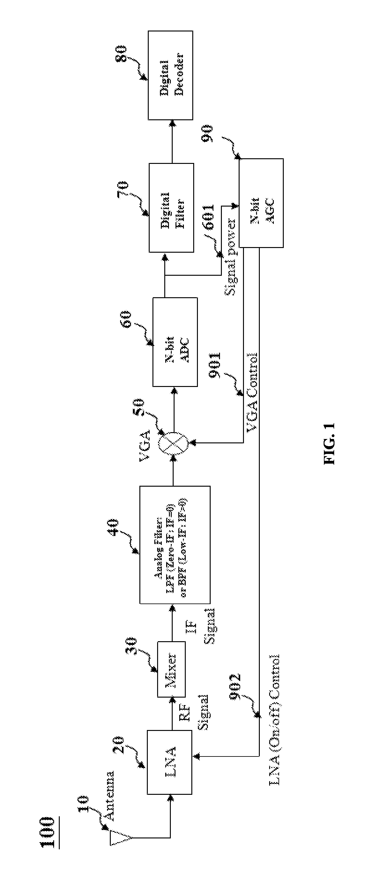
[0016]In short, using a digital circuitry to measure the signal power with accuracy is relatively slower than that by an analog circuitry. However, the digital circuitry is relatively cheaper and consumes less power when compared with an analogy one in the IC design.
[0020]It is an objective of the present invention to provide an adaptive wireless communication receiver. By detecting the presence or absence of the adjacent channel interference (ACI) before the scheduled starting time for receiving a Bluetooth packet [1], and accordingly set the receiver configurations including the filter's pass-band bandwidth (BW), filter's order, the sampling rate or the number of analog-to-digital-converter (ADC) output bits, and the automatic-gain-control (AGC) algorithm to determine the low noise amplifier (LNA) and variable gain amplifier (VGA) settings. Therefore, an adaptive, high cost-performance efficient and power-saving algorithm and apparatus can be achieved.

Problems solved by technology

Therefore, the wide-band (WB) ACI power outside the analog filter pass-band BW can not be measured correctly if measured after an analog filter.
On the other hand, although the second method is not required to implement a bypass option on the analog filter, to measure the analog signal power by an analog circuitry requires significant hardware areas (costs) in the IC design.
In addition, this takes significant power consumption which is not desirable for a mobile device with a limited battery capacity.

Method used


Image

  • Adaptive wireless communication receiver
  • Adaptive wireless communication receiver
  • Adaptive wireless communication receiver

Examples


first embodiment

[0040]The functional block diagram of present invention is illustrated in FIG. 4. Most blocks have the same functionalities as described in the prior art of FIG. 1. The adaptive wireless communication receiver 200 comprises: an antenna 2010, a low noise amplifier (LNA) 2020, a mixer 2030, an adaptive analog filter 2040, a variable gain amplifier (VGA) 2060, a switch 2050, an analog-to-digital converter (ADC) with N-bit output 2070, an automatic gain control (AGC) unit 2080, an adaptive receiver algorithm unit 2090, a digital filter 2100, a digital decoder 2110. The antenna 2010 is used for receiving a radio frequency (RF) signal 2011. The low noise amplifier (LNA) 2020, which is having a first input terminal electrically connected to the antenna 2010, a second input terminal and an output terminal, is used for amplifying the radio frequency (RF) signal 2011 according to a low noise amplifier (LNA) control 2081 signal. The mixer 2030, which is having an input terminal electrically co...

second embodiment

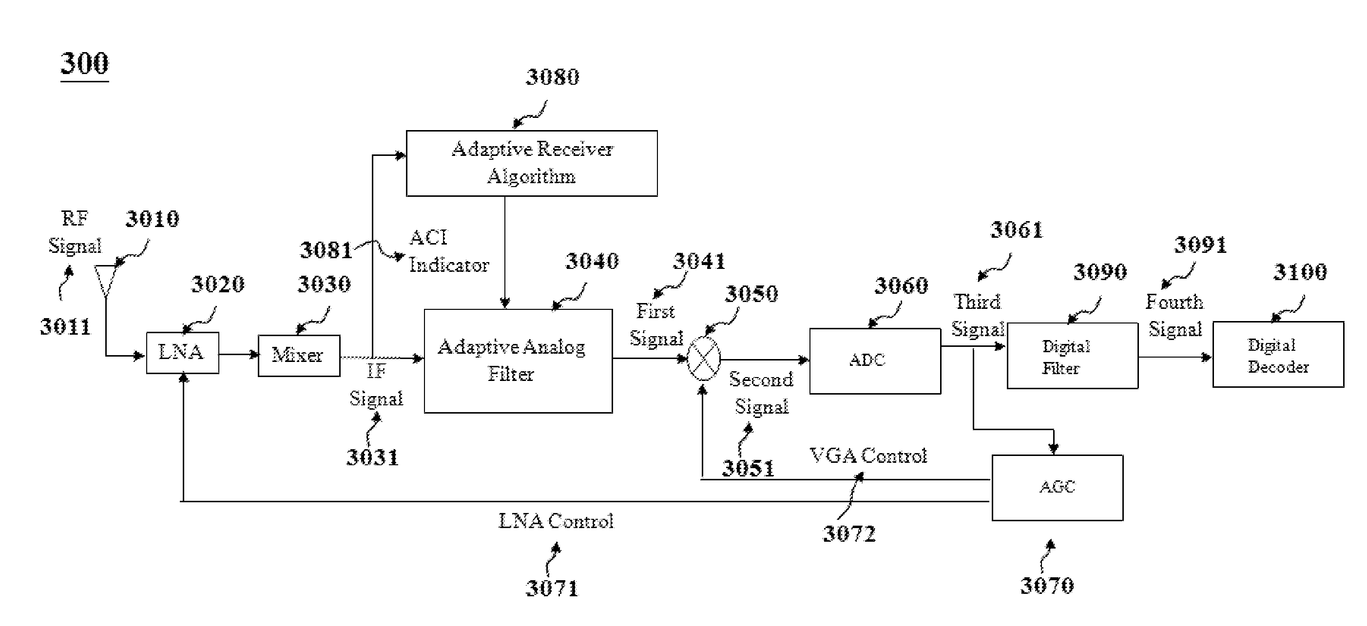
[0042]The functional block diagram of present invention is illustrated in FIG. 5. The adaptive wireless communication receiver 300 comprises: an antenna 3010, a low noise amplifier (LNA) 3020, a mixer 3030, an adaptive analog filter 3040, a variable gain amplifier (VGA) 3050, an analog-to-digital converter (ADC) with N-bit output 3060, an automatic gain control (AGC) unit 3070, an adaptive receiver algorithm unit 3080, a digital filter 3090, a digital decoder 3100.

[0043]The antenna 3010 is used for receiving a radio frequency (RF) signal 3011. The low noise amplifier (LNA) 3020, which is having a first input terminal electrically connected to the antenna 3010, a second input terminal and an output terminal, is used for amplifying the radio frequency (RF) signal 3011 according to a low noise amplifier (LNA) control 3071 signal. The mixer 3030, which is having an input terminal electrically connected to the output terminal of the low noise amplifier (LNA) 3020 and an output terminal, ...

third embodiment

[0045]The functional block diagram of present invention is illustrated in FIG. 6. The adaptive wireless communication receiver 400 comprises: an antenna 4010, a low noise amplifier (LNA) 4020, a mixer 4030, an adaptive analog filter 4040, a variable gain amplifier (VGA) 4060, a switch 4050, an analog-to-digital converter (ADC) with N-bit output 4070, an automatic gain control (AGC) unit 4080, an adaptive receiver algorithm unit 4090, a digital filter 4100, a digital decoder 4110. Most blocks have the same functionalities as described above including an adaptive analog filter 4040. In addition, the switch 4050 is used to select an input signal to the variable gain amplifier (VGA) 4060 before or after the adaptive analog filter 4040, i.e., the intermediate frequency (IF) signal 4031 or the output signal of the adaptive analog filter 4040, respectively, according to a switch control signal 4092 set by the adaptive receiver algorithm unit 4090. The adaptive receiver algorithm unit 4090 ...


PUM


Abstract

The present invention relates to an adaptive, cost-performance efficient, power-saving apparatus for wireless communication systems, such as but not limited to Bluetooth (BT) receivers, and in particular to a packet-based receiver's decoding algorithm which can detect the presence or absence of the adjacent channel interference (ACI) before the scheduled starting time for receiving a Bluetooth packet, and accordingly set the receiver configurations including the filter's pass-band bandwidth (BW), filter's order, the sampling rate, the number of analog-to-digital-converter (ADC) output bits, and the automatic-gain-control (AGC) algorithm unit to determine the low noise amplifier (LNA) and variable gain amplifier (VGA) settings.

Description

BACKGROUND OF THE INVENTION[0001]1. Field of the Invention[0002]The present invention relates to an adaptive, cost-performance efficient, power-saving apparatus for wireless communication systems, such as but not limited to Bluetooth (BT) [1] receivers, and in particular to a packet-based receiver's decoding algorithm which can detect the presence or absence of the adjacent channel interference (ACI) before the scheduled starting time for receiving a Bluetooth packet [1], and accordingly set the receiver configurations including the filter's pass-band bandwidth (BW), filter's order, the sampling rate or the number of analog-to-digital-converter (ADC) output bits, and the automatic-gain-control (AGC) algorithm to determine the Low Noise Amplifier (LNA) and Variable Gain Amplifier (VGA) settings.[0003]2. Background[0004]A Bluetooth device is required to pass the BT specification [1] including the receiver sensitivity and ACI tests. In order to pass the ACI tests, a high order analog f...

Claims


Application Information

Patent Timeline
IPC IPC(8): H04L27/08
CPCH04B1/109Y02B60/50H04B2001/1045
Inventor CHEN, JENG-HONGCHEN, PENG-SENHO, HSIANG-TEHUANG, KUANG-HUHUANG, ZHI-QINGCHANG, CHIN-CHANG
Owner MICROCHIP TECH INC
Learn More