Spiral heat exchanger

a heat exchanger and spiral technology, applied in the direction of indirect heat exchangers, lighting and heating apparatus, stationary plate conduit assemblies, etc., can solve the problems of relative complex manufacturing work needed for connection mounting and difficulty in proper realization, and achieve the effect of easy manner

Inactive Publication Date: 2010-01-05
ALFA LAVAL CORP AB
View PDF17 Cites 17 Cited by
  • Summary
  • Abstract
  • Description
  • Claims
  • Application Information

AI Technical Summary

Benefits of technology

[0006]The object of the present invention is to overcome the problems mentioned above. More specifically, it is aimed at a spiral heat exchanger which permits an elegant layout of the conduits and pipes connected to the heat exchanger and which can be manufactured in an easy manner.
[0013]According to a further embodiment of the present invention, the heat exchanger includes a connection element including the first pipe. Advantageously, the connection element also includes the second pipe and the enclosure. Such a connection element may be manufactured as a separate unit or module, which is introduced into the cylinder after the winding of the sheets to form a spiral heat exchanger element. The connection element may easily be designed in such manner that it may be arbitrarily rotated in relation to the spiral heat exchanger element.

Problems solved by technology

One problem with this conventional spiral heat exchanger is the relatively complex manufacturing work needed for the mounting of the connection pipes extending from the center of the spiral heat exchanger.
In particularly, the problem is related to the difficulty to achieve a proper and desired position for the two connection pipes and the headers at the periphery of the spiral element.

Method used


Image

  • Spiral heat exchanger
  • Spiral heat exchanger
  • Spiral heat exchanger

Examples


Embodiment Construction

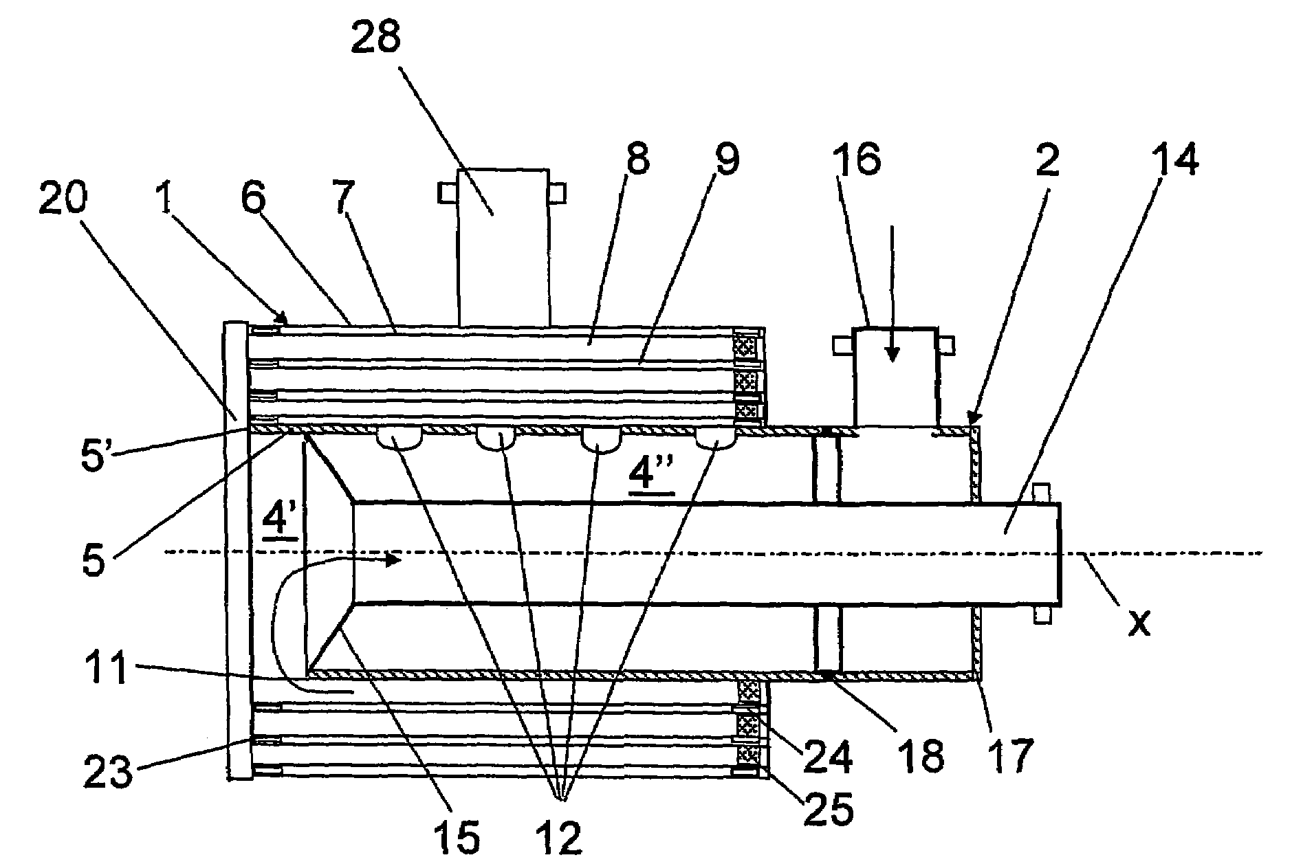
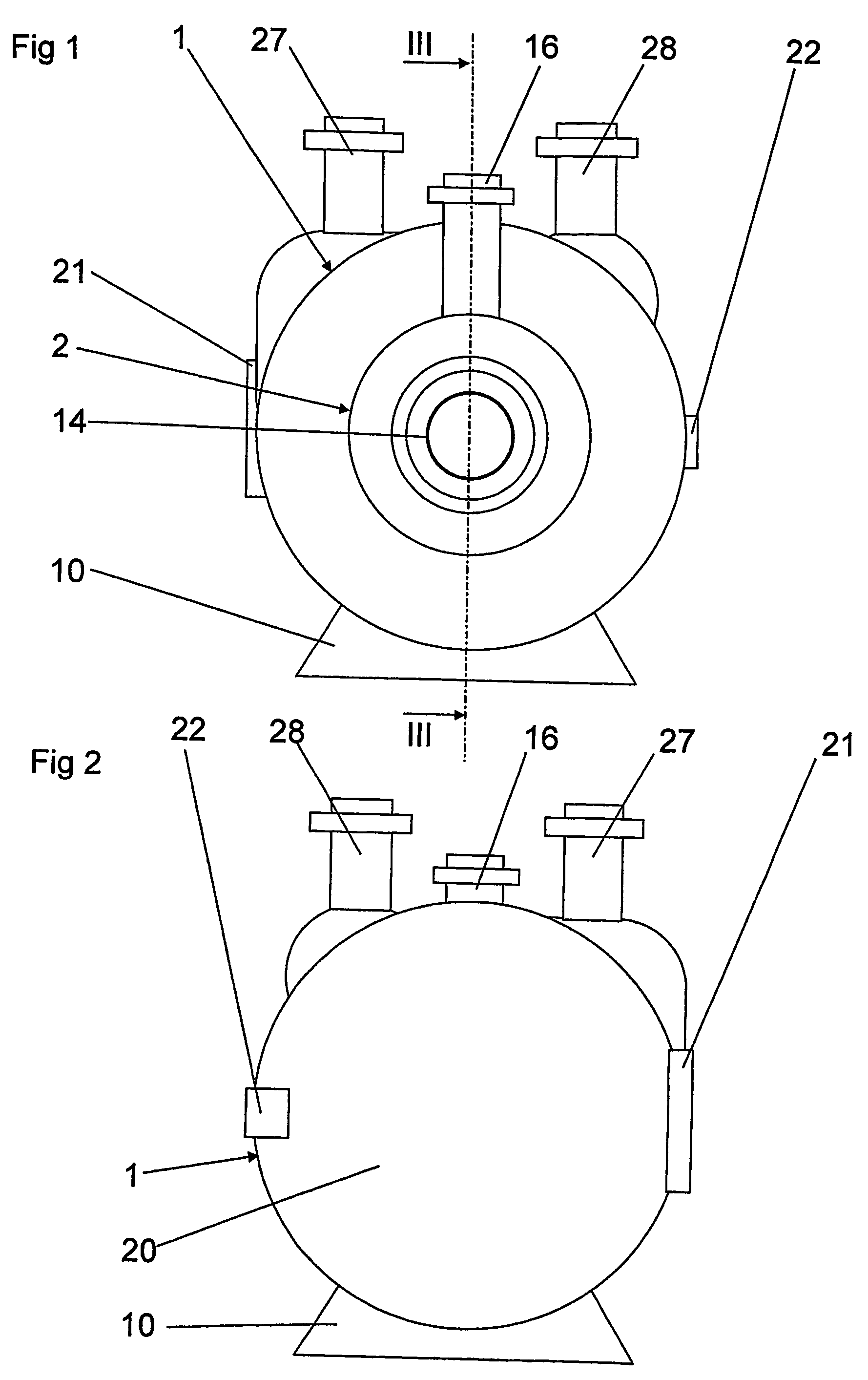
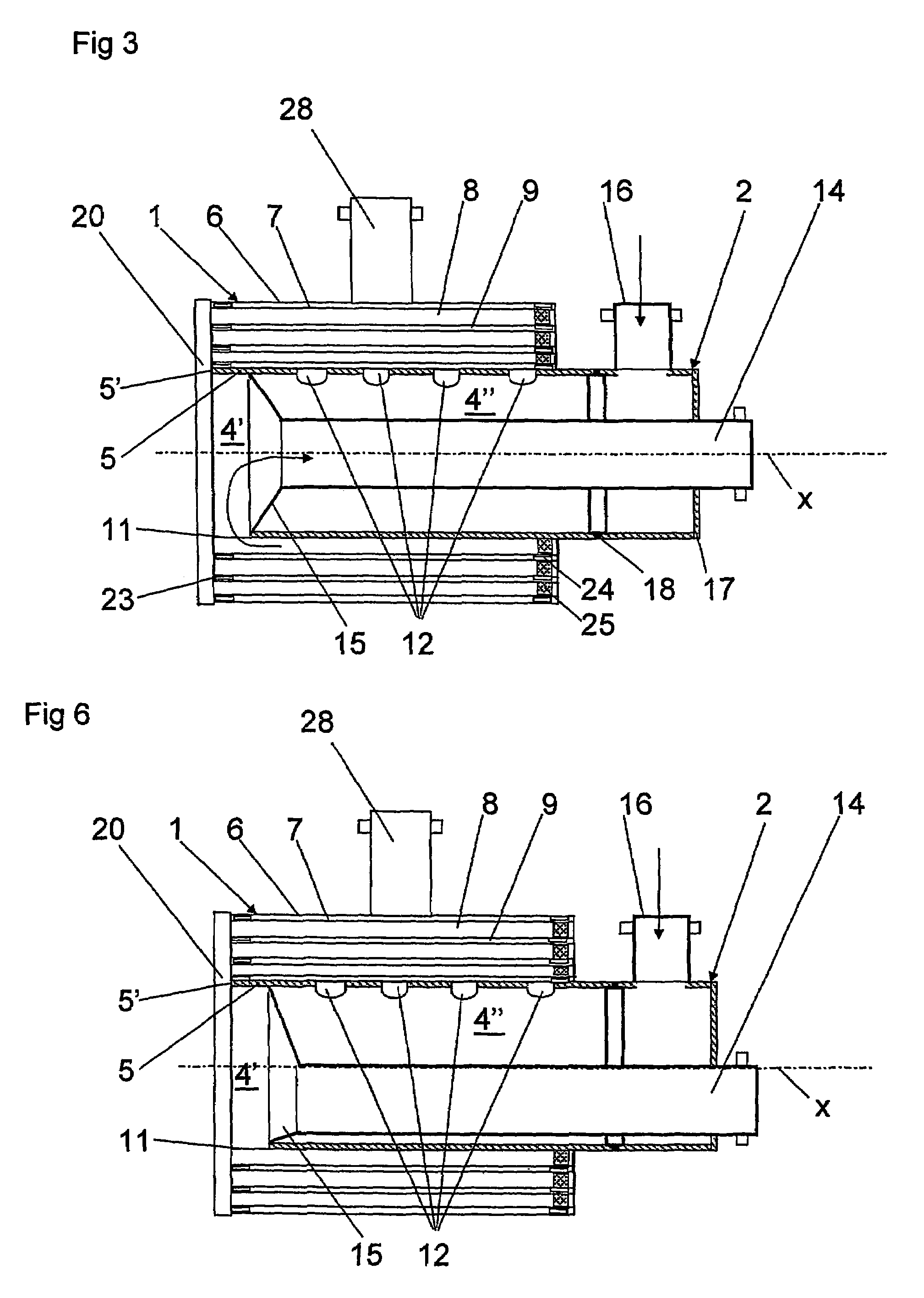
[0025]With reference to FIGS. 1-5, a spiral heat exchanger is disclosed. The spiral heat exchanger includes a spiral heat exchanger element 1, see FIG. 4, and a primary connection element 2, see FIG. 5. In the embodiments disclosed in FIGS. 1 to 6, the primary connection element 2 is designed as a separate unit to be mounted to the spiral heat exchanger element 1. It is to be noted that at least a part of the primary connection element 2, as an alternative, may be an integrated part of the spiral heat exchanger element 1 as explained below.

[0026]The spiral heat exchanger element 1 includes a central cylinder 5 and at least two spiral sheets 6 and 7, preferably of metal, such as stainless steel, carbon steel or titanium. The cylinder 5 has a substantially circular cylindrical shape. Each of the sheets 6, 7 has an inner end edge, which is welded to the outer surface of the cylinder 5. The cylinder 5 is rotated around a center axis x to wind the sheets 6, 7 in such a way that the sheet...


PUM


Abstract

The invention relates to a spiral heat exchanger including a central cylinder (5) and at least two spiral sheets (6, 7). The sheets extend from the cylinder to form a first spiral-shaped flow channel (8) for a first medium and a second spiral-shaped flow channel (9) for a second medium. The cylinder forms an inner space within the cylinder. The cylinder includes a first opening (11) communicating with the first flow channel and a second opening (12) communicating with the second flow channel. A pipe (14) extends into the inner space of the cylinder. A first communication channel, communicating with the first flow channel via the first opening, is formed within the pipe. A second communication channel, communicating with the second flow channel via the second opening, is formed in the inner space outside the pipe.

Description

BACKGROUND OF THE INVENTION AND PRIOR ART[0001]The present invention refers generally to spiral heat exchangers for various purposes. More specifically, the invention refers to a spiral heat exchanger for recovering heat from problematic fluids, such as sludge. In particular, the present invention refers to a spiral heat exchanger including a central cylinder and at least two spiral sheets extending from the cylinder along a respective spiral-shaped path around a common center axis and forming at least a first spiral-shaped flow channel for a first medium and a second spiral-shaped flow channel for a second medium, wherein the cylinder extends around the center axis and forms an inner space within the cylinder, and wherein the cylinder includes a front end, a rear end, at least a first lateral opening communicating with the first flow channel and at least a second lateral opening communicating with the second flow channel.[0002]Such a spiral heat exchanger is disclosed in SE 112 656...

Claims


Application Information

Patent Timeline
Patent Type & Authority Patents(United States)
IPC IPC(8): F28D7/04F28D9/04
CPCF28D9/04Y10S165/398
Inventor MAUPETIT, PHILIPPEMARTINEZ, PIERREOUDJEDI, BOUALEM
Owner ALFA LAVAL CORP AB
Why Eureka
Try Eureka