Vehicle wheel fender flap

a technology for fender flaps and vehicles, applied in the field can solve problems such as the appearance deterioration of wheel fender flaps, and achieve the effect of less susceptible to swinging during driving

Inactive Publication Date: 2010-01-05
KAWASAKI HEAVY IND LTD
View PDF8 Cites 7 Cited by
  • Summary
  • Abstract
  • Description
  • Claims
  • Application Information

AI Technical Summary

Benefits of technology

[0006]In view of the foregoing, the present invention has been devised to provide an improved wheel fender flap that is less susceptible to swinging during driving and, yet, capable of retaining an appealing feature.
[0008]According to the present invention, the wheel fender flap is so designed that the flap body is reinforced by the reinforcement member to increase the rigidity of the wheel fender flap as a whole. Accordingly, the wheel fender flap of the present invention is advantageously prevented from swinging particularly in a direction up and down with respect to the road surface during the drive of the motor vehicle. Also, since the reinforcement member is a member formed separate from the flap body, the possibility of formation of pull-ins by shrinkage, which is often observed when the wheel fender flap is formed integrally with the reinforcement ribs as discussed hereinbefore, can advantageously be eliminated, allowing the wheel fender flap of the present invention to provide an appealing appearance. Considering that the flap body is reinforced by the reinforcement member, a flap body having a relatively low rigidity can be utilized in the practice of the present invention, with the flexibility of design increased consequently.
[0009]In a preferred embodiment of the present invention, the reinforcement member may have a connecting area at an upper end thereof, which area is connected to the elongated flap body by means of a first connecting member which concurrently secures the elongated flap body to the member forming the vehicle body structure. According to this preferred feature, the same connecting member can be concurrently utilized to connect the reinforcement member with the elongated flap body together and also to connect the reinforcement member and the elongated flap body together with the vehicle body structure and, accordingly, not only can the number of component parts used be reduced, but also the structure can be simplified.

Problems solved by technology

However, the molding of the reinforcement ribs integrally with the wheel fender flaps may often leave pull-ins caused by thermal shrinkage in surfaces of the eventually molded wheel fender flaps, which lead to deterioration in appearance of the wheel fender flaps.

Method used


Image

  • Vehicle wheel fender flap
  • Vehicle wheel fender flap
  • Vehicle wheel fender flap

Examples


second embodiment

[0037]FIG. 6 illustrates an perspective exploded view of the reinforcement member employed in the practice of a second preferred embodiment of the present invention. In this second embodiment, a reinforcement member 70A, which is formed independent of and separate from the elongated flap body 60 is employed. This reinforcement member 70A is so shaped and so positioned as to be nested inside the elongated flap body 60 in tight contact with a front surface thereof. The reinforcement member 70A has two mounting holes 75 defined therein. When while the mounting holes 75 are aligned with the mounting holes 67 in the license plate mount 64, corresponding mounting screws 76 are passed from rear through those holes 75 and 67 and associated nuts 78 are fastened from front onto the mounting screws 76, the reinforcement member 70A is secured to the elongated flap body 60 together with the license mounting bracket 65 to thereby reinforce the elongated flap body 60. The reinforcement member 70A ...

first embodiment

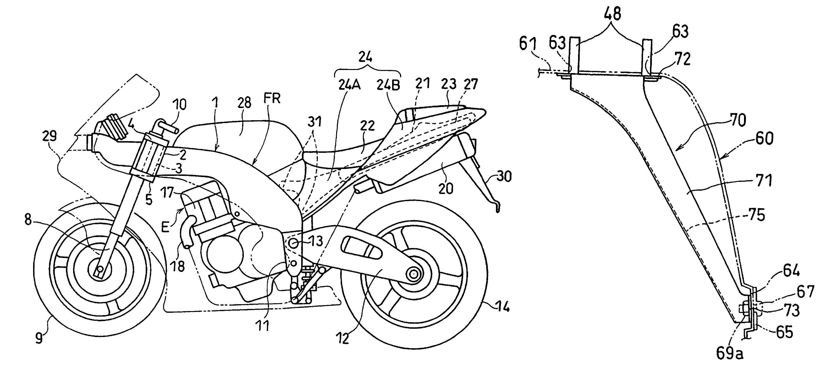
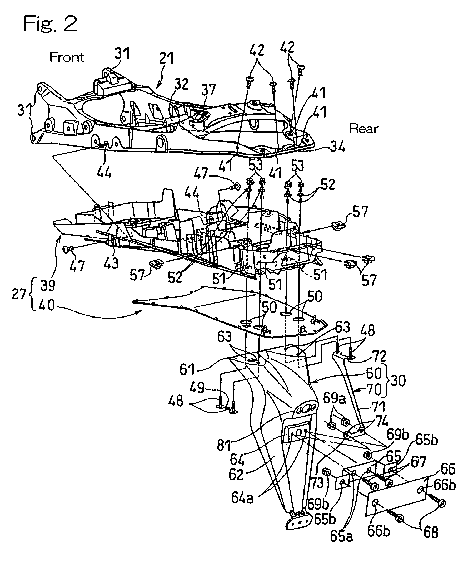
[0039]It is to be noted that although in describing the present invention with particular reference to FIG. 2, one end portion of the reinforcement member 70 has been shown and described as fitted to the elongated flap body 60 together with the license plate mounting bracket 65, which is a member independent of and separate from the fender flap 30, the opposite end portion of the reinforcement member 70 may be fitted to the elongated flap body 60 together with, for example, the license plate illuminator that is mounted in the illuminator mount 81.


PUM


Abstract

To provide a wheel fender flap that is less susceptible to swinging during the use thereof and capable of retaining an appealing feature, the wheel fender flap arranged to confront a vehicle wheel, includes a generally elongated flap body supported by a vehicle body structure and a reinforcement member separate from the flap body, but used to increase the rigidity of the flap body.

Description

BACKGROUND OF THE INVENTION[0001]1. Field of the Invention[0002]The present invention relates to a wheel fender flap that is used over each wheel of a motor vehicle.[0003]2. Description of the Prior Art[0004]As is well known to those skilled in the art, motorcycles, three-wheeled motor vehicles and four-wheeled off-road vehicles are equipped with flaps over wheels of those motor vehicles so as to block the splashing of water and / or mud. An exemplary motorcycle wheel fender flap is disclosed in, for example, the Japanese Laid-open Patent Publication No. 2004-224176, published Aug. 12, 2004. Those flaps are generally made of a synthetic resin.[0005]The wheel fender flaps of the kind referred to above are apt to swing or shake when the motor vehicles drive on a rough road. To suppress the swinging, it may be contemplated to form reinforcement ribs integrally with the wheel fender flaps during the molding of the latter. However, the molding of the reinforcement ribs integrally with the ...

Claims


Application Information

Patent Timeline
Patent Type & Authority Patents(United States)
IPC IPC(8): B62D25/16B62D25/18
CPCB62J15/00
Inventor FUJIMOTO, YUKINORIBEPPU, HIDEOFUJII, KATSUJI
Owner KAWASAKI HEAVY IND LTD
Why Eureka
Try Eureka