Applicator device

a technology of application device and application plate, which is applied in the field of application plate, can solve the problems of difficulty in uniform application of conventional application plate, high difficulty in producing on such a substrate a uniform application, and high difficulty in uniform application of line of a constant line width, so as to achieve the effect of reducing the increase of pressure, increasing pressure, and increasing pressur

Inactive Publication Date: 2010-01-05
SCHWAN STABILO COSMETICS
View PDF20 Cites 22 Cited by
  • Summary
  • Abstract
  • Description
  • Claims
  • Application Information

AI Technical Summary

Benefits of technology

[0005]When the applicator device according to the invention is applied to an easily displaceable substrate such as for example to the skin or a textile-like surface, the application means can elastically recoil in the axial direction without requiring the collaborative involvement of that person who is guiding the applicator device. Particularly when used on the skin, that has the advantage that the male or female user still has to concentrate only on positioning in the plane of the skin. In addition, the risk of injury is minimised in the case of uses in the proximity of the eye.
[0023]In accordance with a particularly preferred embodiment of the invention it is therefore provided that the applicator device can assume at least two operating conditions, namely a rest condition and a use condition, and has a means for reducing the pressure in the storage means, said pressure-reducing means being responsive to a movement of the applicator device from the use condition into the rest condition. In other words, this configuration of the invention provides that the pressure in the storage means is reduced automatically as soon as the applicator device—after its work has been done—is put into the rest condition.

Problems solved by technology

If such an applicator device is used on a substrate which is easily displaceable in the application plane, then conventional applicator devices are not suitable for application thereon because folds are thrown up, that is to say raised portions, which stand up out of the plane of the substrate.
The difficulty of producing on such a substrate a uniform application such as for example a line of a constant line width are similarly high as in the case of a substrate which is structured from the outset—in such a way as to be perceptible to the eye.

Method used


Image

  • Applicator device
  • Applicator device
  • Applicator device

Examples


Embodiment Construction

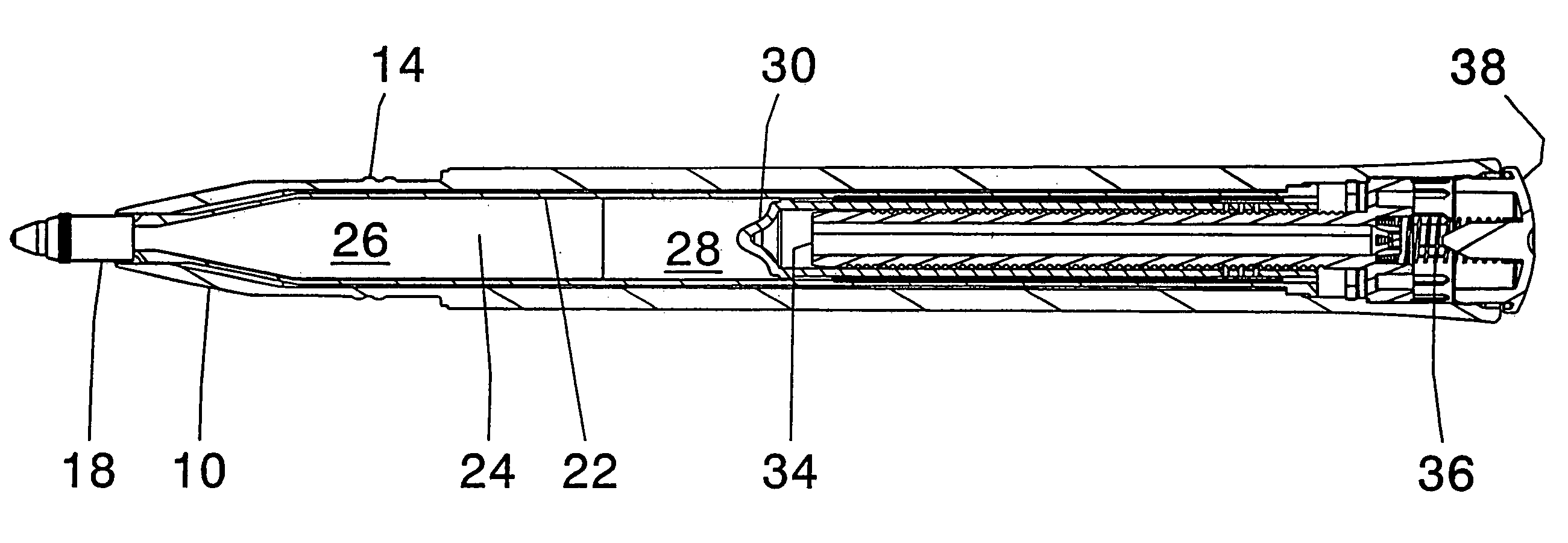
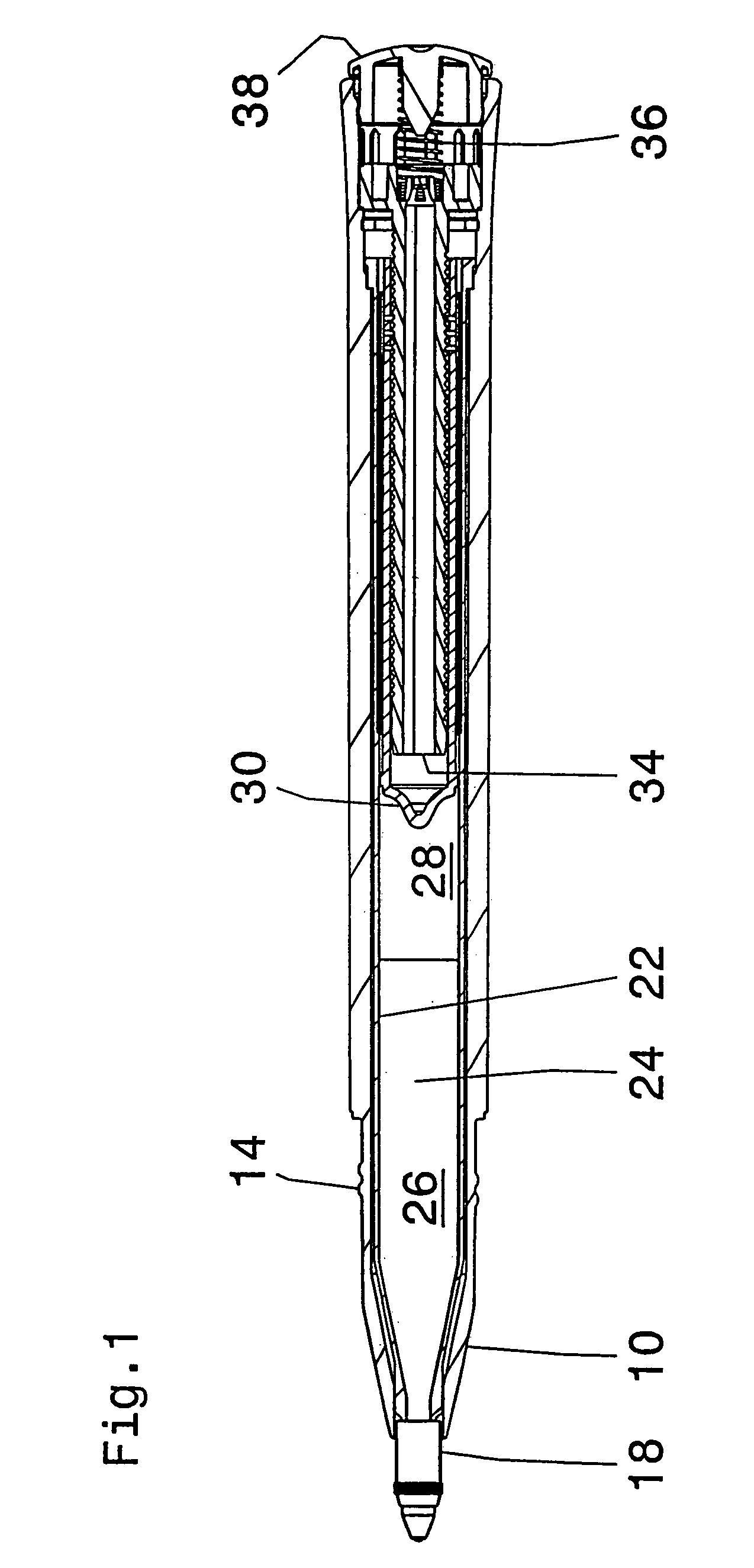
[0045]Referring to the figures, the pencil has an outer shaft 10 which serves as a casing and on to which a cap 12 can be screwed. For that purpose there is provided a screwthread identified by reference numeral 14. The cap 12 has a seal 16 which sealingly embraces a tip 18 of the pencil in the screwed-on condition. A ball 20 is held at the free end of the tip 18. A row of teeth 19 on the cap 12 and a ring of teeth 21 on the pencil serve for rotationally coupling the cap 12 to the tip 18 when it is screwed on.

[0046]At its end portion remote from the ball 20 the tip 18 is fitted on to a lead or cartridge casing portion 22. In that region the tip 18 is of a circular internal contour and the casing portion 22 is also of a circular external contour, thus affording a slipping clutch.

[0047]The internal space of the casing portion 22 forms a storage means 24 for ink 26. Arranged on the side remote from the ball 20 in the storage means 24 is a closure mass which serves for sealing off in re...


PUM


Abstract

An applicator device comprising a casing and an application element wherein the application element is displaceable with respect to the casing against a return force.

Description

BACKGROUND OF THE INVENTION[0001]The invention concerns an applicator device comprising a casing and an application means.[0002]Applicator devices of that kind are known. They involve for example ballpoint pens. If such an applicator device is used on a substrate which is easily displaceable in the application plane, then conventional applicator devices are not suitable for application thereon because folds are thrown up, that is to say raised portions, which stand up out of the plane of the substrate. The difficulty of producing on such a substrate a uniform application such as for example a line of a constant line width are similarly high as in the case of a substrate which is structured from the outset—in such a way as to be perceptible to the eye.[0003]The object of the present invention is to improve the applicator device of the kind set forth in the opening part of this specification, such that it is suitable for substrates which are displaceable in the application plane as we...

Claims


Application Information

Patent Timeline
Patent Type & Authority Patents(United States)
IPC IPC(8): B43K23/08
CPCA45D40/20B43K1/08B43K7/03B43K7/08B43K23/12
Inventor BIEGEL, FRIEDRICH
Owner SCHWAN STABILO COSMETICS
Why Eureka
Try Eureka