Eccentric gear mechanism and method of transfering turning force thereby

a gear mechanism and eccentric gear technology, applied in the direction of toothed gearings, belts/chains/gearings, toothed gearings, etc., can solve the problems of reducing the total ratio and creating unwanted vibrations at high speed, and achieve the effect of eliminating usual vibrations and avoiding vibrations

Active Publication Date: 2010-01-05
HYTORC DIV UNEX CORP
View PDF21 Cites 44 Cited by
  • Summary
  • Abstract
  • Description
  • Claims
  • Application Information

AI Technical Summary

Benefits of technology

[0014]In order to avoid vibrations when the tool provided with the inventive eccentric gear mechanism is powered by a high speed motor, the centrally located eccentric drive can be weight-balanced to assure that the eccentric drive during its turning motion is balanced to the point that the usual vibrations are eliminated.

Problems solved by technology

In particular, they create unwanted vibrations at high speed.
While this is not a problem with a tool having just a single eccentric gear mechanism as the direction of the input drive can be switched, it is a problem when two or more eccentric gear mechanisms are placed on top of each other or one eccentric gear mechanism is placed on top of planetary gear stages to obtain a high ratio, because unlike the planetary gear mechanism, the eccentric gear mechanism can not use in its outer, centrally located ring gear as the reaction absorbing part, because it would decrease the total ratio by the ratio of the eccentric gear mechanism.

Method used


Image

  • Eccentric gear mechanism and method of transfering turning force thereby
  • Eccentric gear mechanism and method of transfering turning force thereby
  • Eccentric gear mechanism and method of transfering turning force thereby

Examples


Embodiment Construction

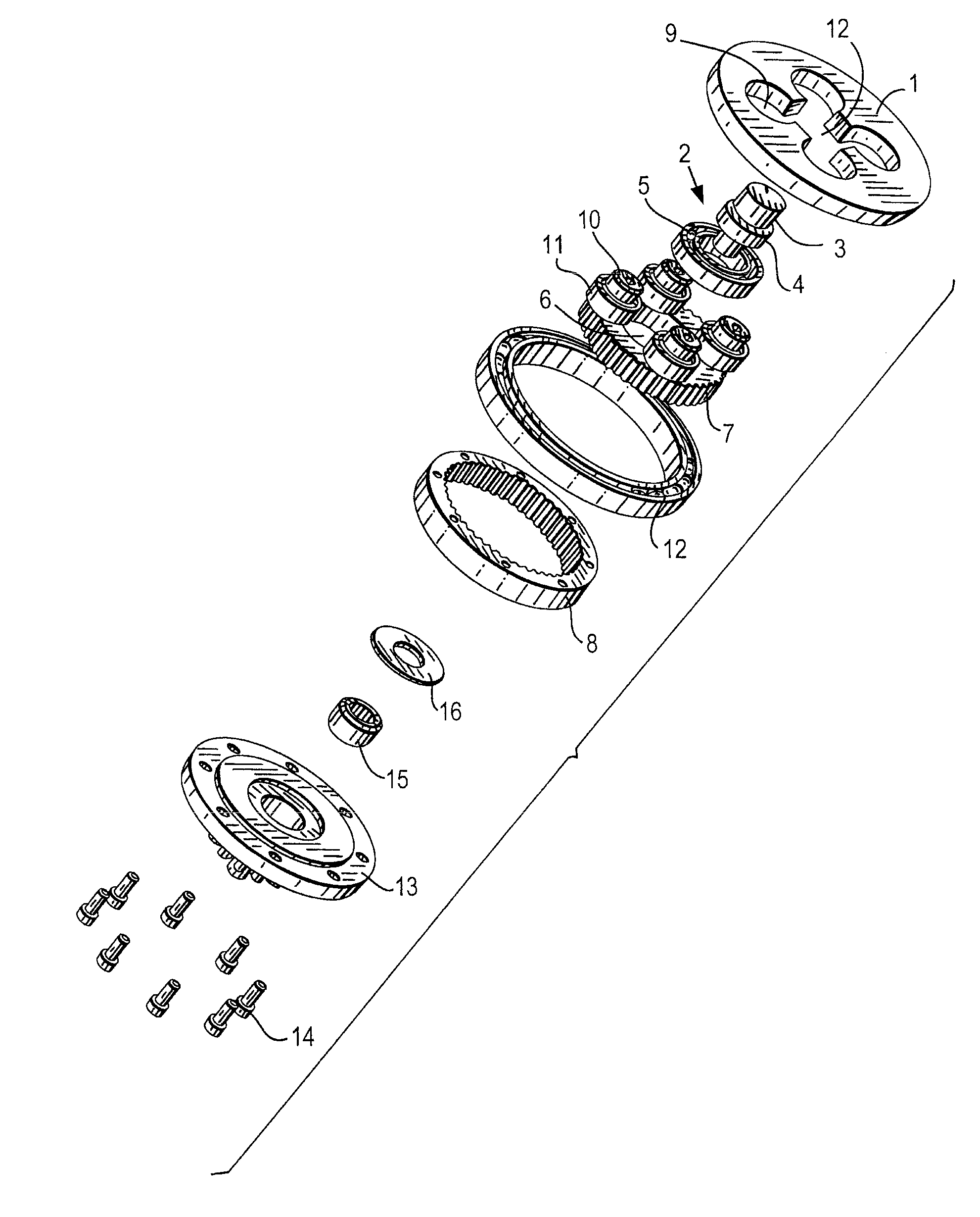
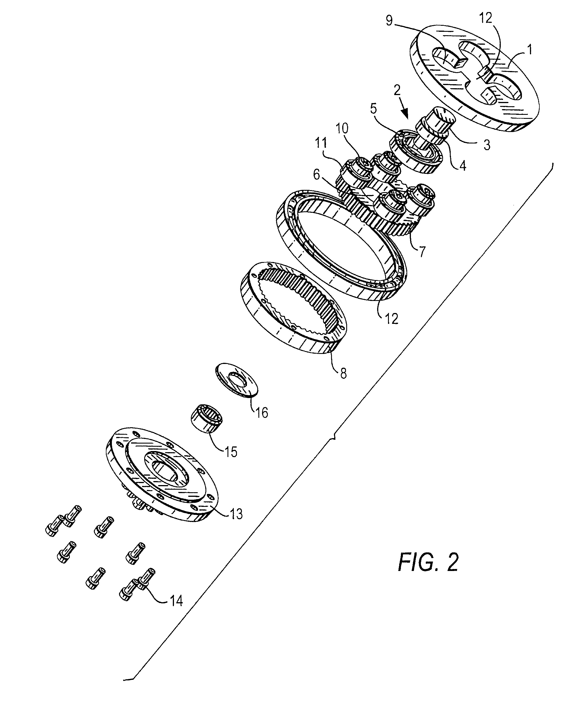
[0020]An eccentric gear mechanism in accordance with the present invention has an immovable, non-rotatable housing 1 which can be formed for example as a lid, or as a housing to which the stationary lid is immovably, non-rotatably connected.

[0021]The inventive eccentric gear mechanism further has an input drive which is identified as a whole with reference numeral 2. The input drive has a centric portion which forms an input shaft 3 and is rotated from outside around an axis A. The input drive 2 has an eccentric portion, formed for example as an eccentric cam 4.

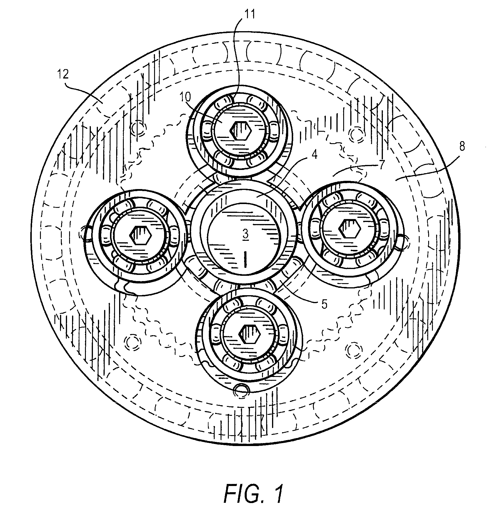
[0022]The eccentric cam 4 is provided with a bearing 5. It is insertable with the bearing 5 into an inner opening 6 of an inner ring gear 7. The inner ring gear 7 has outer gear teeth provided on its outer circumference.

[0023]The eccentric gear mechanism further has an outer ring gear 8 provided with inner gear teeth on its inner circumference. The outer gear teeth of the inner ring gear 7 engage partially with the inner gear...


PUM


Abstract

An eccentric gear mechanism, comprising an input drive having a centric portion rotated about an axis and an eccentric portion; a movable inner ring gear having outer circumferential gear teeth, so that said centric portion and said eccentric portion of said input drive turn in one direction against said movable inner ring gear, said inner ring gear being configured in such a way that it allows an eccentric movement by said inner ring gear and transfers a given turning force derived by said inner ring gear in an opposite direction to said one direction; an outer ring gear having inner circumferential gear teeth partially engaged with said outer circumferential gear teeth of said inner ring gear, so that when said given turning force is derived by said inner gear ring in said opposite direction said outer ring gear rotates around said axis, and said outer ring gear transfers said given turning force in said one direction outwardly along said axis.

Description

BACKGROUND OF THE INVENTION[0001]The present invention relates to eccentric gear mechanisms, and methods of transferring turning forces thereby.[0002]Eccentric gear mechanisms are known in the art. An eccentric gear mechanism is known which includes an inner ring gear with outer gear teeth provided on its outer circumference, an outer ring gear with inner gear teeth provided on its inner circumference and engaging with the outer gear teeth of the inner ring gear, and means for generating an eccentric movement between the gears.[0003]The known eccentric gear mechanisms usually have some disadvantages. In particular, they create unwanted vibrations at high speed. The known eccentric gear mechanism turns an inner ring gear, which moves against the outer, centrally located ring gear, so that the outer ring gear turns in the same direction as the eccentric sun drive and the inner ring gear in the opposite direction unlike planet gears. This means that action and reaction are reversed. Wh...

Claims


Application Information

Patent Timeline
Patent Type & Authority Patents(United States)
IPC IPC(8): F16H1/32
CPCF16H1/32F16H1/28
Inventor JUNKERS, JOHN K.
Owner HYTORC DIV UNEX CORP
Why Eureka
Try Eureka