Supercharge Your Innovation With Domain-Expert AI Agents!

Push-button arrangement and push-button

a technology of push-button and button, which is applied in the direction of electric switches, basic electric elements, electric apparatus, etc., can solve the problems of preventing affecting the operation of the button, so as to improve the finger contact and quick and easy manufacturing

Inactive Publication Date: 2010-01-05
SANDVIK MINING & CONSTR OY
View PDF16 Cites 6 Cited by
  • Summary
  • Abstract
  • Description
  • Claims
  • Application Information

AI Technical Summary

Benefits of technology

The invention provides a push-button arrangement and a push-button that have improved sealing properties. The push-button arrangement includes a fastening hole in the fastening plate with conical sealing surfaces that seal with the push-button. The outer surface of the fastening sleeve portion also has conical sealing surfaces that press against the sealing surfaces of the fastening hole. This sealing arrangement prevents impurities and moisture from entering the inner surface side of the fastening plate. The push-button is simple and inexpensive to manufacture and is easy to install. The invention also provides a push-button with a protrusion for improved finger contact and a symbol to indicate the purpose of use. The push-button is interconnected by a common fastening flange and can be shaped as desired.

Problems solved by technology

A problem with current pushbuttons is that impurities and moisture may enter through the buttons inside the control equipment.
Moreover, the impurities between a push-button and the housing of the control equipment may jam the button and prevent its operation.
Although prior art knows buttons tightly enclosed under a protective film, finger contact with these buttons and their functionality is considered poor.

Method used


Image

  • Push-button arrangement and push-button
  • Push-button arrangement and push-button
  • Push-button arrangement and push-button

Examples


Embodiment Construction

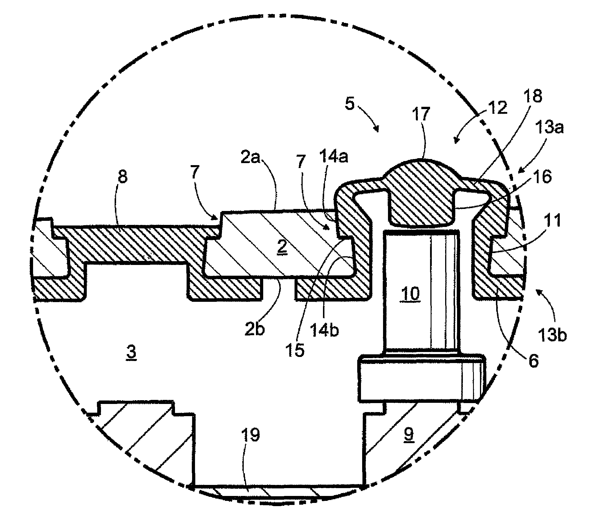
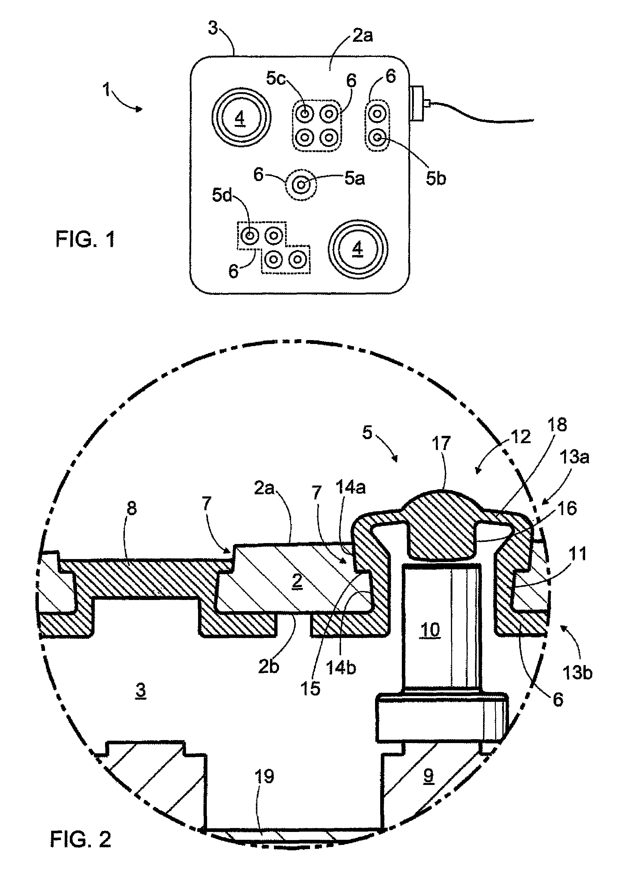
[0026]FIG. 1 shows control equipment 1 for controlling the operations of a machine at work. The machine in question may be for example a rock drilling rig, mining vehicle, excavator, forestry machine, hauling device, or the like. The control equipment 1 may be a box-type piece with a fastening plate 2 on the upper surface thereof. Underneath the fastening plate 2 there may be a component space 3 with the necessary switches and electrical components arranged therein. The fastening plate 2 may be provided with one or more control members, such as control sticks 4, wheels, rolls or balls arranged on the outer surface side thereof. In addition, the control equipment 1 may comprise one or more push-buttons 5. With the control members the machine operator may submit control commands to the control unit of the machine or directly to its actuators.

[0027]FIG. 1 shows different alternative push-buttons 5. The button may be an individual push-button 5a, a combination 5b of two buttons or a mat...


PUM


Abstract

A push-button arrangement and a push-button. The push-button comprises a fastening sleeve portion having a press portion at a first end thereof and a fastening member at a second end thereof for connecting the push-button to a fastening hole in a fastening plate. The outer surface of the fastening sleeve portion is provided with at least one conical sealing surface and the fastening hole, correspondingly, with a conical counter surface.

Description

CROSS REFERENCE TO RELATED APPLICATIONS[0001]This application is the National Stage of International Application No. PCT / FI2007 / 050076, filed Feb. 13, 2007, and claims benefit of Finnish Application No. 20065111, filed Feb. 14, 2006.BACKGROUND OF THE INVENTION[0002]The invention relates to a push-button arrangement comprising: at least one fastening plate having an outer surface and an inner surface; at least one fastening hole in the fastening plate; a switch arranged at the at least one fastening hole, on the inner surface side of the fastening plate; at least one push-button made substantially entirely of an elastic material; a fastening portion for fastening the push-button to the fastening hole in the fastening plate; and the fastening portion comprising at least one fastening sleeve portion with an annular cross-section and an outer surface arranged against the fastening hole; and the push-button comprising a press portion; and the fastening sleeve portion having at least one ...

Claims


Application Information

Patent Timeline
Patent Type & Authority Patents(United States)
IPC IPC(8): H01H13/06
CPCH01H13/06H01H2009/048H01H9/04
Inventor VIRTANEN, ISTOKARVONEN, TONIKUMANTO, EEROMURANEN, MARTTI
Owner SANDVIK MINING & CONSTR OY
Features
  • R&D
  • Intellectual Property
  • Life Sciences
  • Materials
  • Tech Scout
  • Unparalleled Data Quality
  • Higher Quality Content
  • 60% Fewer Hallucinations
Learn More