
High efficiency ferrite antenna system

a ferrite antenna and high-efficiency technology, applied in the direction of antennas, antenna details, electrically short antennas, etc., can solve the problems of voiding the warranty on the radio and/or wiring system, people may be reluctant to have the internal wiring redone by an outside vendor, and being somewhat expensiv

Inactive Publication Date: 2010-01-05
IRVINE COMPANY LLC THE
View PDF5 Cites 5 Cited by
  • Summary
  • Abstract
  • Description
  • Claims
  • Application Information

AI Technical Summary

Benefits of technology

Enables the use of compact antennas that can be easily integrated into devices, providing strong FM signal reception with low noise ratios and automatic tuning to adjust for frequency changes, thus overcoming the limitations of traditional antenna systems in size, cost, and complexity.

Problems solved by technology

As navigation systems presently are installed primarily in newer and more expensive cars, people may be reluctant to have the internal wiring redone by an outside vendor.
Further, such rewiring can void the warranty on the radio and / or wiring system, and can be somewhat expensive.
Some manufacturers use proprietary devices, such as amplifiers and amplifier systems, which may not function properly after such an installation.
Further still, sharing the antenna can result in a reduction in quality of the existing radio, as the shared antenna typically introduces additional noise into the FM signal input to the radio.
In automobiles, these antennas are subject to breakage and can be somewhat unsightly.
The antennas can be included in the glass or other areas or devices of the vehicles, but this increases the cost and complexity of these parts.
In handheld FM radios, the earphone wires often are used as the antenna, which has not proven to provide optimal reception.
Further, portable radios often require an extendable antenna, which may not be practical for systems places in areas with minimal space, such as a bookshelf or cabinet.

Method used


Image

  • High efficiency ferrite antenna system
  • High efficiency ferrite antenna system
  • High efficiency ferrite antenna system

Examples


Embodiment Construction

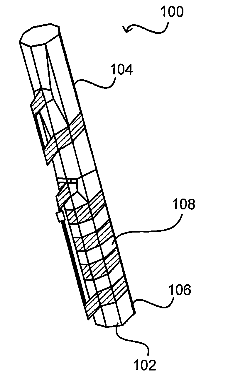
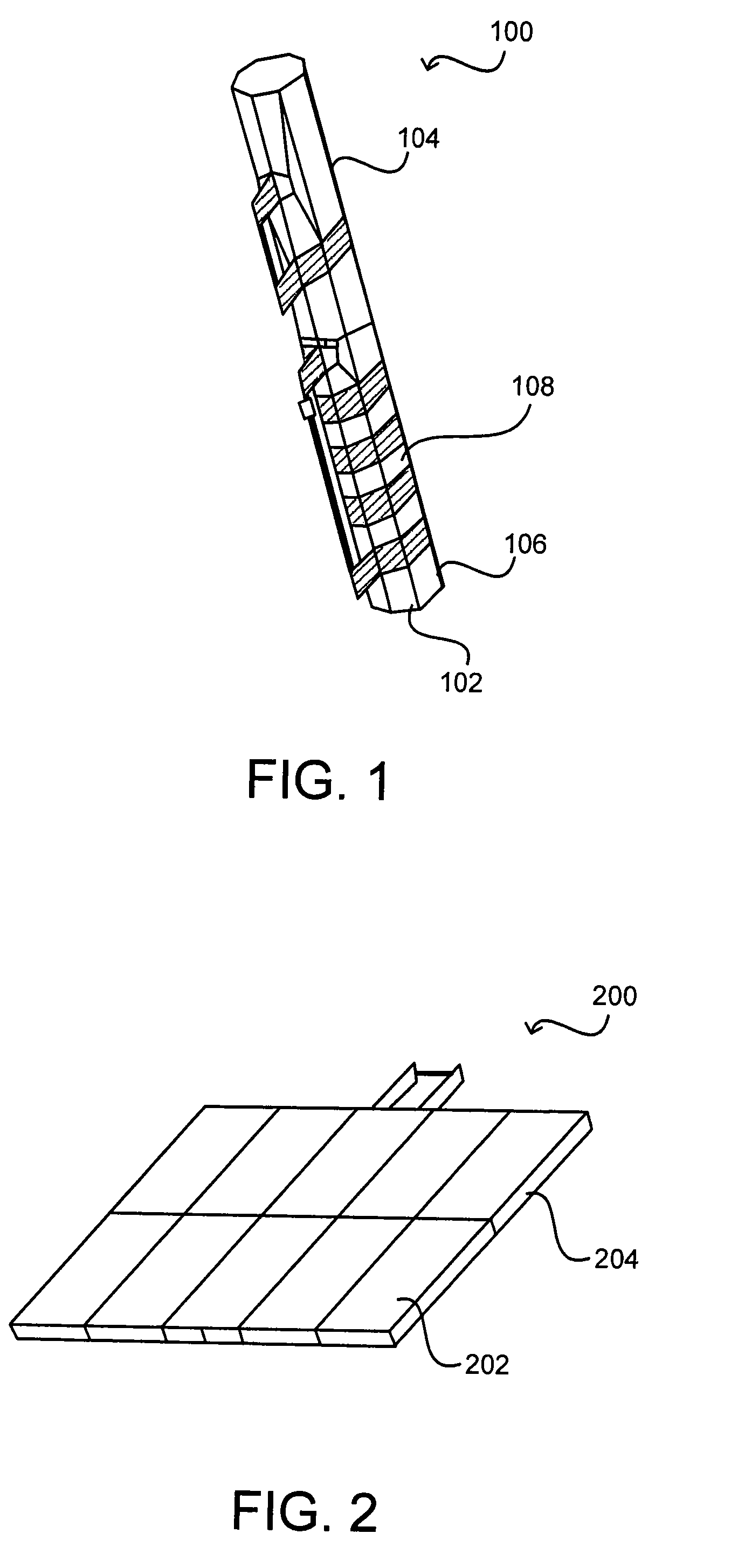
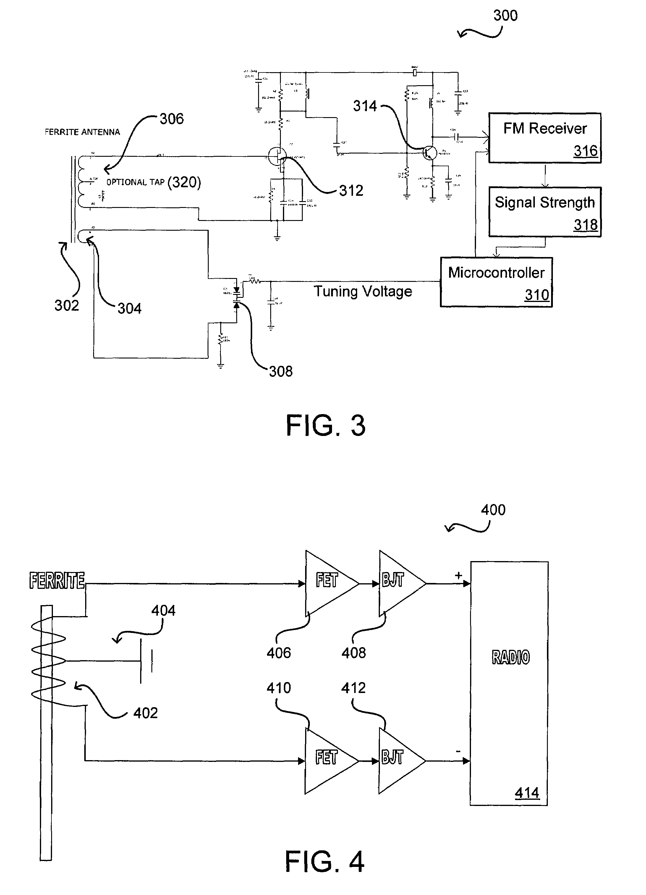
[0019]Systems and methods in accordance with various embodiments of the present invention can overcome these and other deficiencies in existing FM antenna applications by providing for reduced antenna sizes that can be automatically tuned to provide desirable results. In one embodiment, a ferrite rod or disk antenna can be used with a microcontroller system to provide an antenna that is about an inch in length that can easily be incorporated into a device such as an FM radio or navigation system. The microcontroller can provide for automatic tuning of the antenna at various FM frequencies. The antennas themselves provide characteristics allowing the systems to provide the necessary signal strengths, with sufficiently low signal to noise ratios, when properly tuned using the microcontroller system. Such antennas can be used in any application where it is desirable to utilize a small antenna for bands with relatively long wavelengths, such as FM bands.

[0020]For example, FIG. 1 illustr...


PUM


Abstract

An automatic tuning procedure can be used to allow a small, high efficiency ferrite antenna assembly to be used in various FM frequency based devices. The ferrite antenna can take the form of a rod or flat disk, for example, which can use a pick-up coil and tuning coil to provide sufficient signal strength using a small FM antenna. A balanced amplifier can be used to provide differential input in order to further reduce noise. A microcontroller can determine the strength of the FM signal at various frequencies and can automatically tune the operating frequency to optimize system performance.

Description

CROSS-REFERENCE TO RELATED APPLICATIONS[0001]This application claims priority to U.S. Provisional Patent Application Ser. No. 60 / 764,139, filed Jan. 31, 2006, entitled “HIGH EFFICIENCY FERRITE ANTENNA SYSTEM,” which is hereby incorporated herein by reference.BACKGROUND OF THE INVENTION[0002]An increasing number of automobiles and other vehicles are including devices such as navigation systems, which use satellite or GPS information to track and provide navigation information to the driver. Some of these systems also provide additional “real-time” information, such as traffic information or gas price information, which is added on top of the geographic data displayed to the driver. While some systems utilize satellite radio signals, others utilize common FM frequencies. When common FM frequencies are used, a common quarter-wave antenna typically is needed to pick up the signal with acceptable strength. Since an FM frequency of about 100 MHz has a quarter wavelength of about 31 inches...

Claims


Application Information

Patent Timeline
Patent Type & Authority Patents(United States)
IPC IPC(8): H01Q7/08
CPCH01Q7/005H01Q7/08
Inventor DAVIS, STEVEN JAY
Owner IRVINE COMPANY LLC THE
Learn More