Housing for chemical irritant dispenser

a technology of chemical irritant spray and canister, which is applied in the field of non-lethal weapons, can solve the problems of difficult actuation when mounted on side arms, the housing mechanism that actuates the canister, and the general failure of the canister, so as to achieve convenient actuation, convenient triggering, and convenient firing.

Inactive Publication Date: 2010-01-12
LAW ENFORCEMENT ASSOC
View PDF21 Cites 23 Cited by
  • Summary
  • Abstract
  • Description
  • Claims
  • Application Information

AI Technical Summary

Benefits of technology

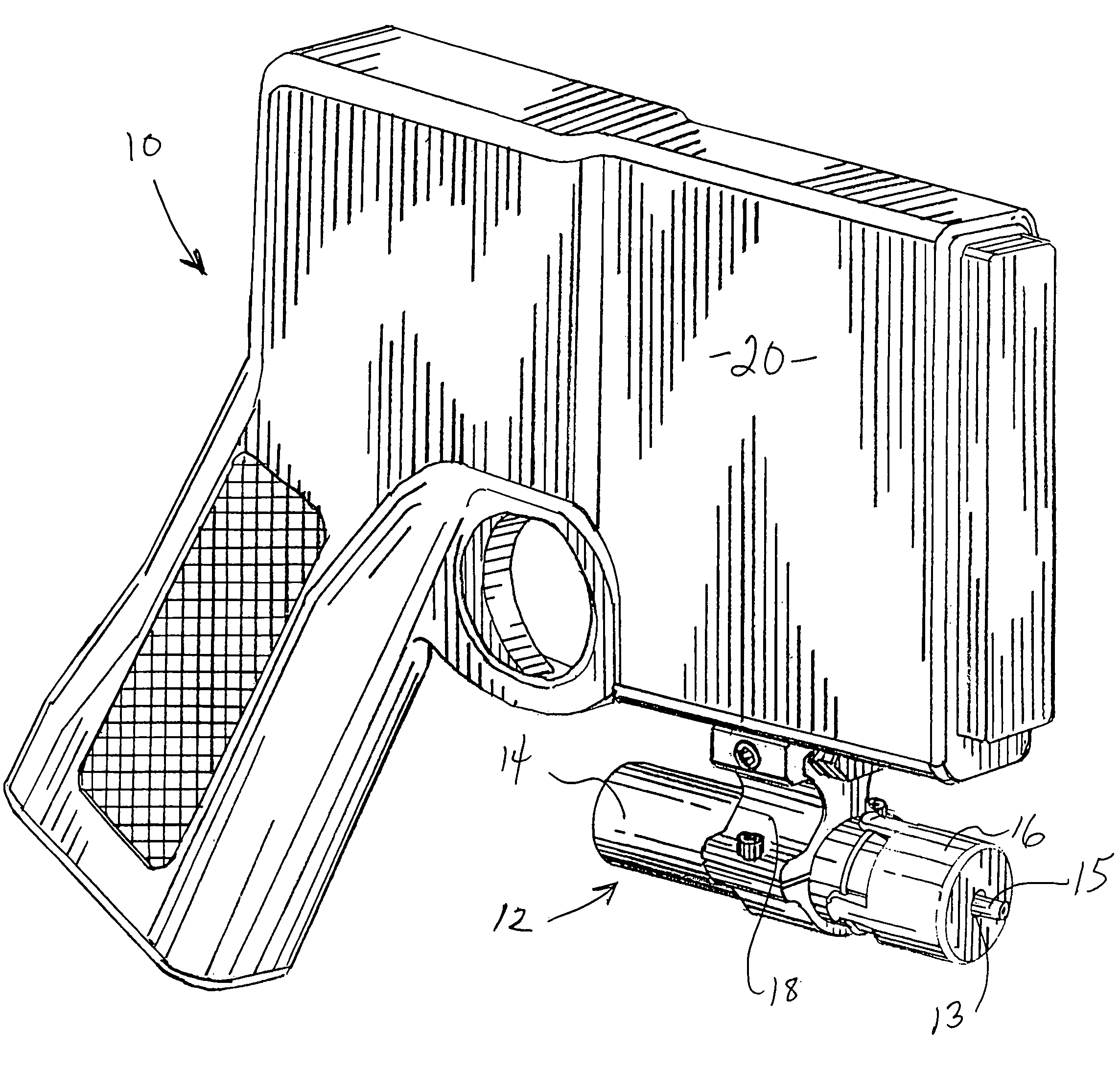
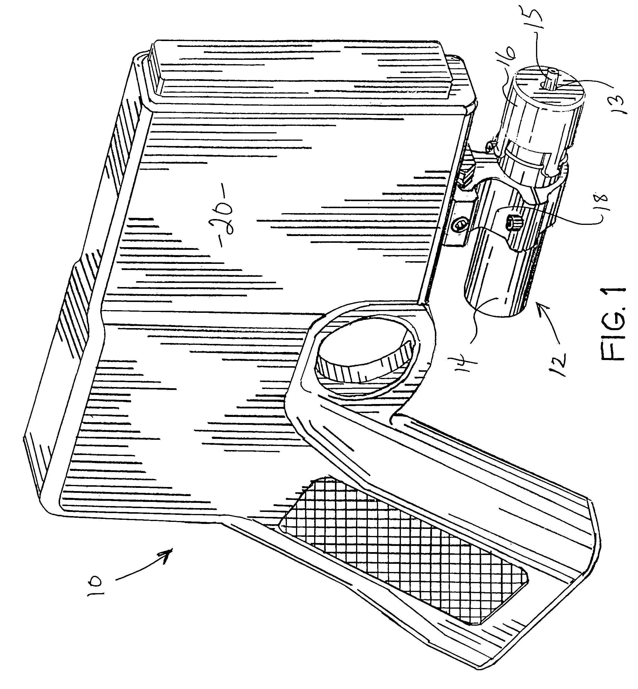
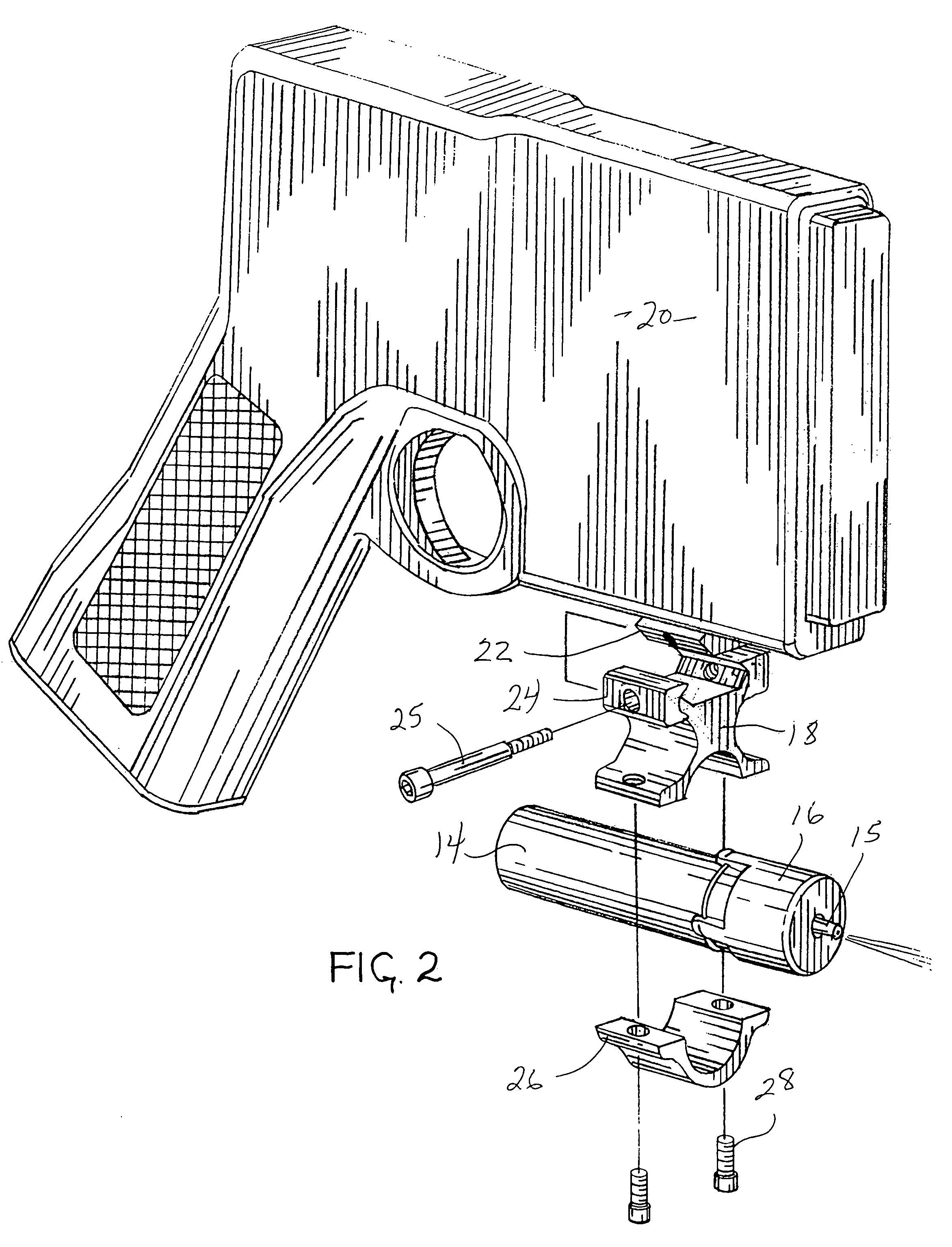
[0010]The invention comprises a novel canister housing which can be mounted to a pistol or other weapon and conveniently fired therefrom and which can also be used as a discrete weapon itself. The invention consists of a cap, which has a central aperture which secures the nozzle and / or valve stem of a canister of chemical irritant from movement and which can, itself, be secured to the proximal end of a hollow tube. This is a prior art feature that allows for more accurate aiming of the chemical spray. A feature of the new invention is a slot access running along the length of the tube for some distance from its distal end. The tube may be either open or closed at its distal end. Toward the distal end of the tube, there may exist an interior ridge or stop, which cooperates with the cap aperture to secure the canister of irritant. When a canister of chemical irritant is installed in the housing, the operator can manually release a spray of irritant from the canister by pressing a digit of one of his hands against the side of canister's storage cylinder and, thereby, displace its longitudinal axis along an arc. For this unique method of releasing the spray axially from its canister, the housing need have no moving parts or triggers or other mechanisms, except the housing and canister themselves. This unique method also allows for the convenient triggering of a release of a spray from a canister of irritant within the housing when the housing is secured under or adjacent to the barrel of a handgun. A door may cover the slot and in some embodiments an actuator compresses against a spring-loaded pusher to contact the side of the canister or storage cylinder and move the longitudinal axis of the canister or storage cylinder to release a spray.
[0011]In the preferred embodiments, the tube is a hollow cylinder. In one embodiment, the tube is a hollow cylinder, and the cap is thread connected to the tube. In a second embodiment, the tube is also a hollow cylinder, but a catch and ridge structure secures the cap to the housing. In each embodiment, the tube may have a slot which begins at its distal end and extends along the tube. At the proximal end of the tube a plurality of catches and one ridge, which are all of equal width and which are placed equidistantly around the tube, secure the tube to the cap. The tube exterior has a ridge circumferentially around the proximal end for receiving each catch. The catches can now be alternatively seated to allow convenient right, left or center triggering of a handgun mounted canister and housing combination. Each embodiment is shown with hardware for mounting the housing to a gun rail. In both embodiments, the tube has an interior recess or slot to reduce the likelihood of inadvertent impact discharges from the canister. In another illustrative embodiment, the tube is a rectangular housing which is secured to a rectangular cap by two tongue and groove catches. In each embodiment, the slot may travel a short distance up the tube length or along the entire length of the tube.
[0012]A small canister of irritant containing 4.5 grams of law enforcement strength nonflammable pepper spray with a heat rating off 2 million SHU, such as sold by Spitfire, Ltd., 8868 Research Boulevard, No. 203, Austin, Tex. 78758, is placed or replaced into the housing. These canisters can release adequate sprays of debilitating irritant in a cone pattern to a distance of about 8 feet.

Problems solved by technology

However, the housing mechanisms that actuate a canister to release a spray of chemical irritant, are subject to failure generally and difficult to actuate when mounted on side arms.

Method used


Image

  • Housing for chemical irritant dispenser
  • Housing for chemical irritant dispenser
  • Housing for chemical irritant dispenser

Examples


second embodiment

[0027]FIG. 5 illustrates a second embodiment using a tube 14′ and a cap 16′ which have mutually threaded ends for threading engagement of the tube and cap.

third embodiment

[0028]FIGS. 6 and 7 illustrate a third embodiment wherein tube 14′ of FIG. 5 is replaced by a tube 14″ which uses an elongated slotted opening 38 instead of activator 30 of FIG. 5. Opening 38 permits direct contact with canister 17 so that it can be directly displaced by the force of a finger through the opening for releasing the irritant spray through nozzle 15.

[0029]FIG. 8 illustrates yet another embodiment of the inventive housing hereof wherein a rectangular tube 40 cooperates with a rectangular cap 42 and is attached to weapon 20 by a suitably altered rail attachment assembly 44. A side oriented elongated slot 46 provides access to displace canister 17 to release a spray of irritant through nozzle 15. Cap 42 is snap-fit attached to tube 40 using a pair of ridges 48 and a catch 50 extended from opposed surfaces of the cap.


PUM


Abstract

A housing can be mounted to a pistol or other weapon and conveniently fired therefrom and can be used as a discrete weapon itself. A cap has a central aperture which secures the nozzle and / or valve stem of a canister of chemical irritant from movement and is secured to the proximal end of a hollow tube. A feature of the new invention is a slot access running along the length of the tube for some distance from its distal end. The tube may be either open or closed at its distal end. Toward the distal end of the tube, an interior ridge or stop cooperates with the cap aperture to secure the canister of irritant. When a canister is installed in the housing, the operator can release an irritant spray axially from the canister by pressing a digit against the side of the canister's storage cylinder and, thereby, displace its longitudinal axis along an arc. The housing need have no other mechanisms, except the housing and canister. This method also allows for convenient triggering of a spray from a canister within the housing when the housing is secured under or adjacent to the barrel of a handgun. In some embodiments an actuator compresses against a spring-loaded pusher to contact the side of the storage cylinder and move the longitudinal axis of the storage cylinder to release a spray.

Description

BACKGROUND OF THE INVENITON[0001]1. Field of the Invention[0002]The present invention relates to the field of non-lethal weapons which may be attached to another weapon such as a sidearm. The invention herein relates more particularly to a housing for a canister of chemical irritant spray.[0003]2. Background Art[0004]Handheld canisters, which release chemical irritants, like CS, CN (Chloroacetophenone) and OC (Oleoresin Capsicum) sprays have existed for some time. The canisters comprise a storage cylinder which contains a reservoir of irritant under pressure, a sealing valve and a valve stem, and sometimes a nozzle for directing the spray either radially or axially from the valve opening. When an operator's thumb thrusts the canister's valve stem (or its nozzle, if the nozzle either contacts or can be made to contact the valve stem) downward towards the storage cylinder (compresses the valve) and / or when an operator's thumb forces the longitudinal axis of the valve stem (or its nozz...

Claims


Application Information

Patent Timeline
Patent Type & Authority Patents(United States)
IPC IPC(8): A63H3/18B67D7/84
CPCF41B9/00F41C27/06F41G11/001F41G11/004F41H9/10
Inventor MCNULTY, JR., JAMES F.
Owner LAW ENFORCEMENT ASSOC
Why Eureka
Try Eureka