Optical head device and disk drive device

a technology of optical head and disk drive, which is applied in the direction of optical recording head, data recording, instruments, etc., can solve the problems of insufficient cooling effect, insufficient heat radiation effect, and and achieve the effect of insufficient heat radiation

Inactive Publication Date: 2010-01-12
SANKYO SEIKI MFG CO LTD
View PDF4 Cites 2 Cited by
  • Summary
  • Abstract
  • Description
  • Claims
  • Application Information

AI Technical Summary

Benefits of technology

[0015]In view of the problems described above, an embodiment of the present invention may advantageously provide an optical head device in which a sufficient heat radiation effect is obtained in a frame type of laser beam emitting element even when the size of its heat radiating fin is reduced.
[0016]In view of the problems described above, another embodiment of the present invention may advantageously provide an optical head device which is capable of preventing positional displacement of an optical element due to heat generated in a laser driver IC to restrain effects to an optical characteristic and, in which a sufficient heat radiation effect is obtained even when the size of its heat radiating fin is reduced, and may advantageously provide a disk drive device on which the optical head device is mounted.

Problems solved by technology

However, with the miniaturization and thinning of an optical head device, since the light emitting element holder 9 is downsized, heat radiation can not be performed sufficiently even when such the light emitting element holder 9 is used.
Therefore, although its outer shape is large, a sufficient heat radiation area is not obtained and thus heat radiation effect is not satisfactory.
In addition, in a thin-type of optical head device used in a notebook-sized personal computer or the like, the heat radiation member is not exposed from an opening of a tray on which an optical disk is placed and thus cooling effect is not sufficient.

Method used


Image

  • Optical head device and disk drive device
  • Optical head device and disk drive device
  • Optical head device and disk drive device

Examples


Embodiment Construction

[0048]An optical head device in accordance with an embodiment of the present invention will be described below with reference to the accompanying drawings. In this specification, a side on which an objective lens is viewed is defined as an upper face side and the opposite side is defined as an under face side.

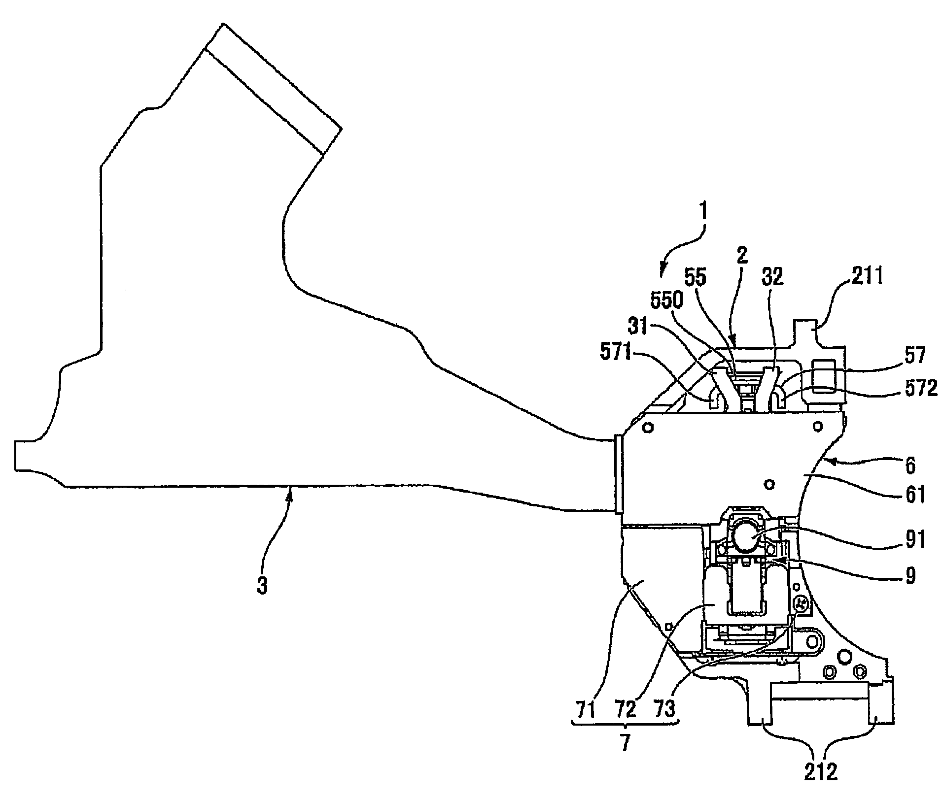
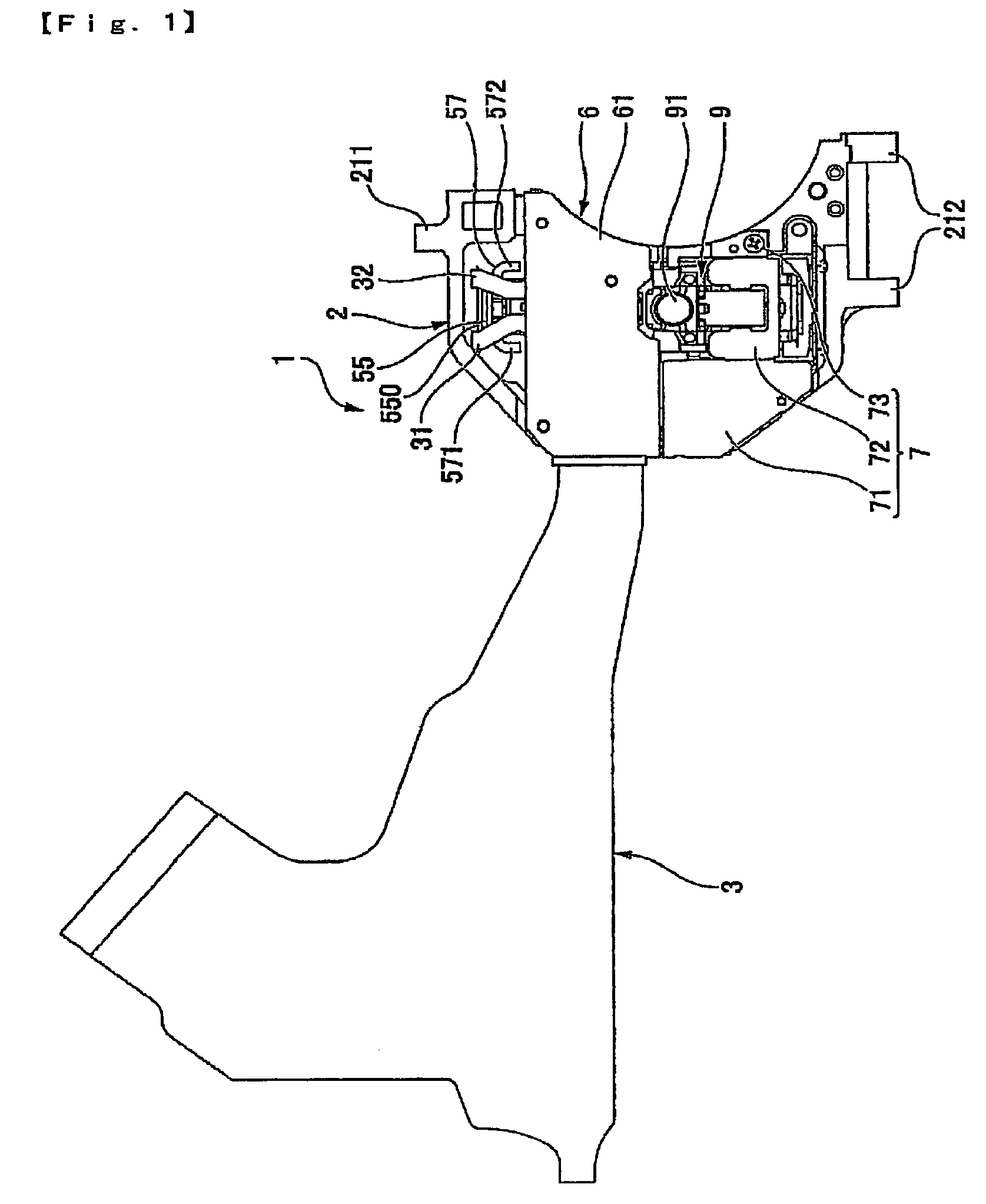
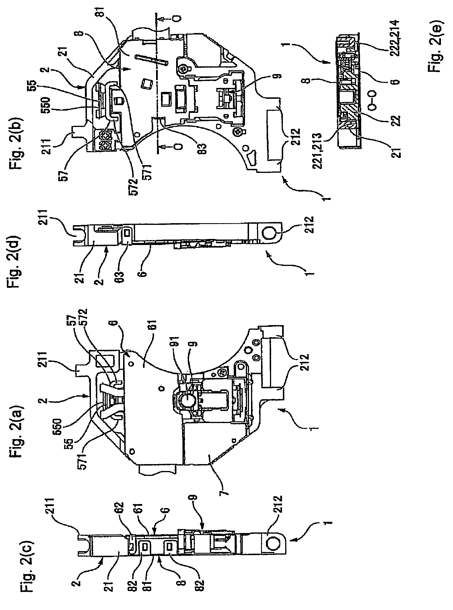
[0049]FIG. 1 is a plan view showing an optical head device in accordance with an embodiment of the present invention. FIG. 2(a) is a plan view showing an enlarged main body portion of the optical head device shown in FIG. 1 in which a flexible circuit board is not shown, FIG. 2(b) is its bottom view, FIG. 2(c) is its left side view, FIG. 2(d) is its right side view, and FIG. 2(e) is an “O-O” cross-sectional view in FIG. 2(b). FIG. 3(a) is a plan view showing a state in which an upper cover, an under cover and an actuator cover are detached from the main body portion of the optical head device shown in FIG. 1 and FIG. 3(b) is its bottom view. FIG. 4(a) is a plan view showing a s...


PUM

PropertyMeasurementUnit
wavelengthaaaaaaaaaa
optical pathaaaaaaaaaa

Abstract

An optical head device may include a frame type of laser beam emitting element provided with a heat radiating fin on which a laser chip is mounted, a device frame on which the laser beam emitting element, a light receiving element and an optical system are mounted, and a heat radiation member formed of material having a superior heat conduction property. The upper face of the laser beam emitting element is fixed to the device frame, and an under face of the heat radiating fin which corresponds to a portion where the laser chip is mounted is exposed on an outer side to form an exposed part, and the heat radiation member is disposed to extend over the exposed part and the device frame. The device frame may include a first protective cover covering the optical disk side of the optical elements, and a second protective cover which covers the optical disk side of the objective lens drive mechanism and which is separately formed from the first protective cover and made of material having a superior heat conduction property, and a part of the second protective cover is extended to a laser driver IC, which is disposed to be exposed on the optical disk side, to form a heat radiation part where heat generated in the laser driver IC is radiated.

Description

[0001]The present invention claims priority under 35 U.S.C. §119 to Japanese Application No. 2005-373736 filed Dec. 27, 2005 and Japanese Application No. 2005-373827 filed Dec. 27, 2005, both of which are incorporated herein by reference.FIELD OF THE INVENTION[0002]An embodiment of the present invention may relate to an optical head device which is used for recording or reproducing information into or from an optical disk such as a CD or a DVD. More specifically, an embodiment of the present invention may relate to a heat radiation structure for a frame type of laser beam emitting element provided in the optical head device and may relate to a heat radiation structure for a laser driver which drives a laser beam emitting element provided in the optical head device.BACKGROUND OF THE INVENTION[0003]A conventional optical head device which is used for reproducing information from an optical disk such as a CD or a DVD includes a laser beam emitting element, an objective lens drive mecha...

Claims


Application Information

Patent Timeline
Patent Type & Authority Patents(United States)
IPC IPC(8): G11B5/10
CPCG11B7/12
Inventor WADE, TATSUKIKASUGA, TAKAFUMISHIRAKI, TAKAHIRO
Owner SANKYO SEIKI MFG CO LTD
Why Eureka
Try Eureka