
Method for exception-based notification of the condition of an apparatus

a technology of exception-based notification and apparatus, applied in the field of transformer management and fault monitoring systems, can solve the problems of destroying the use of on-line monitoring systems, unable to detect certain conditions, and facing too little information

Active Publication Date: 2010-01-12
ARIZONA PUBLIC SERVICE
View PDF16 Cites 20 Cited by
  • Summary
  • Abstract
  • Description
  • Claims
  • Application Information

AI Technical Summary

Benefits of technology

"The present invention provides a method and system for selectively notifying a condition of an apparatus. The system receives data elements from monitoring devices and processes them to detect abnormal conditions of the apparatus. The system determines that the condition is an exception to the normal condition and sends a first notice to a responsible party at the first instance of determination. The system prevents sending a second notice at a second instance of determination, even if it occurs after the first instance. The technical effect of this invention is that it allows for timely notification of abnormal conditions of an apparatus without overwhelming the responsible party with unnecessary information."

Problems solved by technology

Human nature and workload can cause otherwise responsible individuals to postpone analysis of a group of samples due to the repetitive nature of the samples from the on-line DGA monitoring units.
The usefulness of an on-line monitoring system can thus be defeated when the enormous quantity of data is not examined in a timely manner.
Consequently, the utility is typically faced with too little information for a variety of apparatuses because it cannot adequately collect and filter the data into manageable and useful information.
Under these circumstances, certain conditions can go undetected until a catastrophic event occurs.
However, the effectiveness of dissolved gas analysis is limited by the ability to properly disseminate the results of the dissolved gas analysis.

Method used


Image

  • Method for exception-based notification of the condition of an apparatus
  • Method for exception-based notification of the condition of an apparatus
  • Method for exception-based notification of the condition of an apparatus

Examples


Embodiment Construction

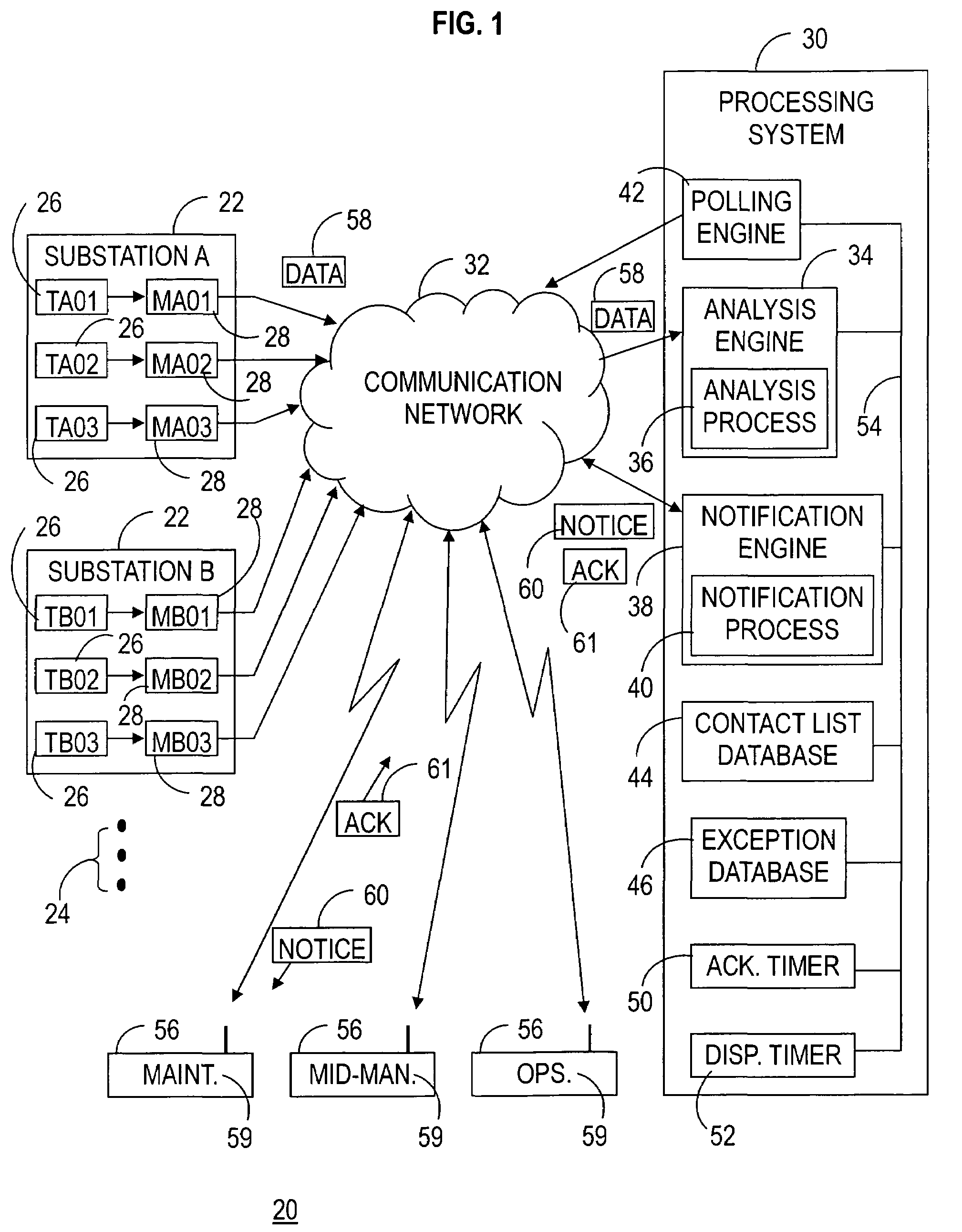
[0023]The present invention entails an exception-based notification method and system for selectively notifying a responsible party of an exception, i.e., a fault condition and severity level, in an apparatus. The notification method and system are described in connection with monitoring of fault conditions in extra high voltage (EHV) transformers located at substations of an electric utility company. Monitoring is performed by dissolved gas analysis (DGA) units, one or more of the DGA units performing on-line monitoring of one each of the transformers. A notification engine in accordance with the present invention communicates a notice of an exception to the appropriate responsible party without inundating the responsible party and other parties with unnecessary and / or repetitive information. It should become readily apparent in the ensuing discussion that the present invention may be readily adapted to a variety of environments in which vast quantities of data are being collected ...


PUM


Abstract

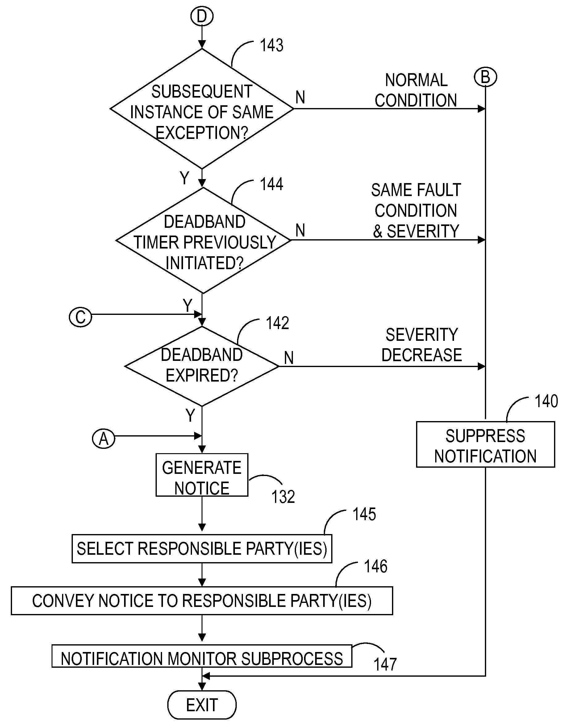
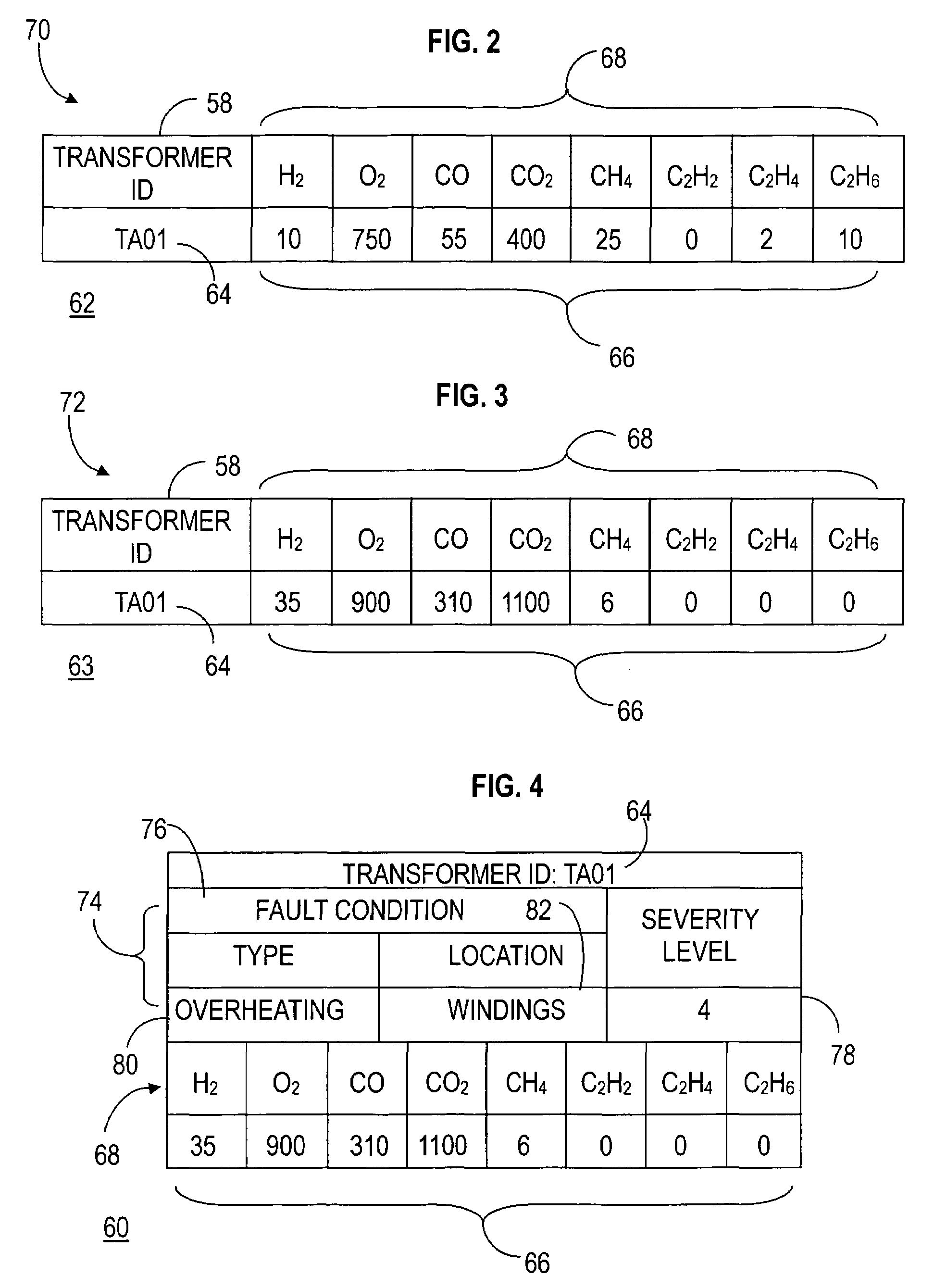
A system (30) includes an analysis engine (34) and a notification engine (38) for selective notification of a condition (72) of an apparatus (26) monitored by a monitoring device (28). A method executed by the system (30) receives (116) data elements (58) from the monitoring device (28), processes (118) the data elements (58) to detect the condition (72) of the apparatus (26), and determines that the condition (72) defines an exception (74) to a normal condition (70) of the apparatus (26). A first notice (60) of the condition (72) is conveyed (146) to a responsible party (59) at a first instance of determination of the exception (74), and conveyance of a second notice (60) is prevented (140) at a second, subsequent, instance of determination of the exception (74). In addition, communication of the normal condition (70) of the apparatus (26) is prevented.

Description

TECHNICAL FIELD OF THE INVENTION[0001]The present invention relates to the field of transformer management and fault monitoring systems. More specifically, the present invention relates to the selective notification of fault conditions in transformer systems.BACKGROUND OF THE INVENTION[0002]Electric power transmission is a process in the delivery of electricity to consumers. In general, the term “electric power transmission” refers to the bulk transfer of electrical power from place to place, for example, between a power plant and a substation near a populated area. Due to the large amount of power involved, electric transmission normally takes place at high voltage (110 kV or above). Transformers are used at the substations to step the voltage down to a lower voltage for distribution to commercial and residential users.[0003]Major power transformers are filled with a fluid, typically of a mineral oil origin, that generally serves as a dielectric media, an insulator, and a heat tran...

Claims


Application Information

Patent Timeline
Patent Type & Authority Patents(United States)
IPC IPC(8): G06F19/00G06F17/40
CPCH02H5/08H02H7/04G05B21/00G05B15/00G05B15/02
Inventor LAMONTAGNE, DONALD R.
Owner ARIZONA PUBLIC SERVICE
Learn More