Electric connector with shields on mating housings

a technology of shields and connectors, applied in the direction of coupling contact members, coupling device connections, coupling protective earth/shielding arrangements, etc., can solve the problem of difficult to absorb positional offset, and achieve the effect of reducing the effect of electromagnetic waves and increasing the reliability of connection

Active Publication Date: 2010-01-26
IRISO ELECTRONICS CO LTD
View PDF4 Cites 11 Cited by
  • Summary
  • Abstract
  • Description
  • Claims
  • Application Information

AI Technical Summary

Benefits of technology

[0012]According to the present invention, the second housing can be moved with respect to the first housing. Thus, if a positional offset occurs between the one connection object and the other connection object, the positional offset can be absorbed. Therefore, it is possible to increase the reliability of connection. In addition, since an EMI measure for the first and second housings can be taken, it is possible to reliably reduce the effect of electromagnetic waves.

Problems solved by technology

However, the connector has a problem in that when the second housing is mated with the first housing, the second shield member is formed so as to be engaged in a predetermined position of the first shield member and thus the second housing cannot be moved in a state where the second housing is mated with the first housing and if a positional offset occurs between one connection object and the other connection object, it is difficult to absorb the positional offset.

Method used


Image

  • Electric connector with shields on mating housings
  • Electric connector with shields on mating housings
  • Electric connector with shields on mating housings

Examples


Embodiment Construction

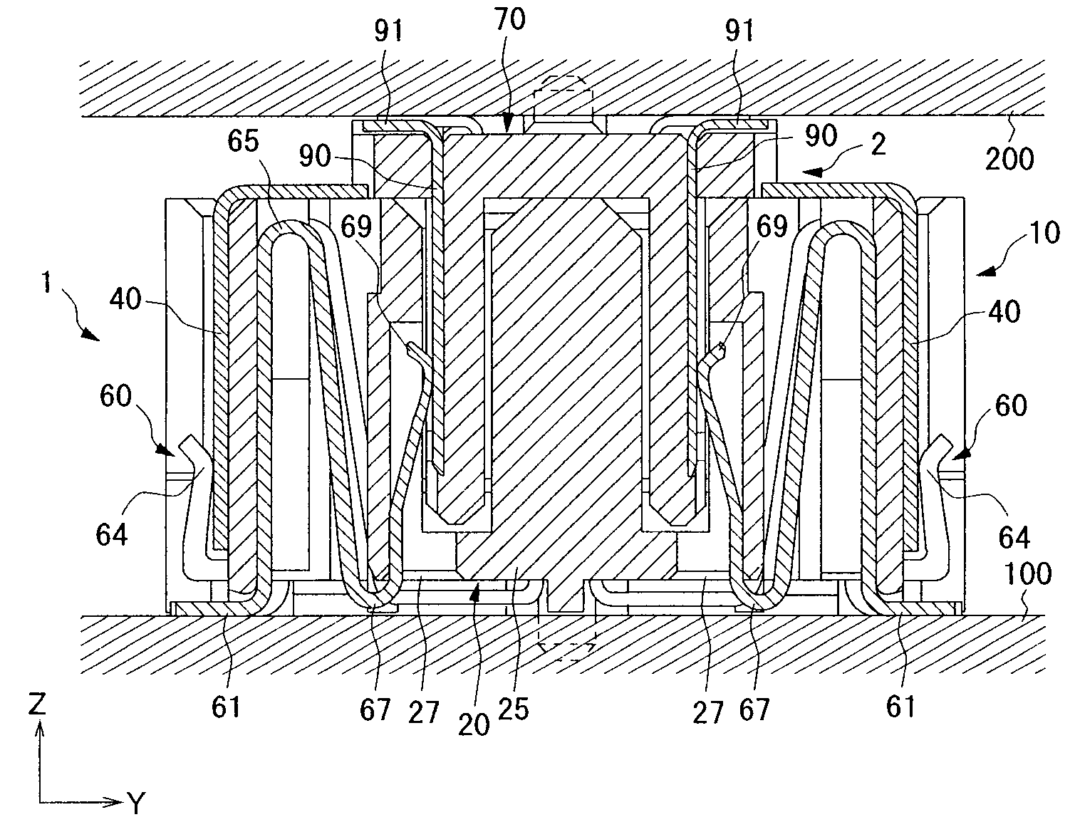
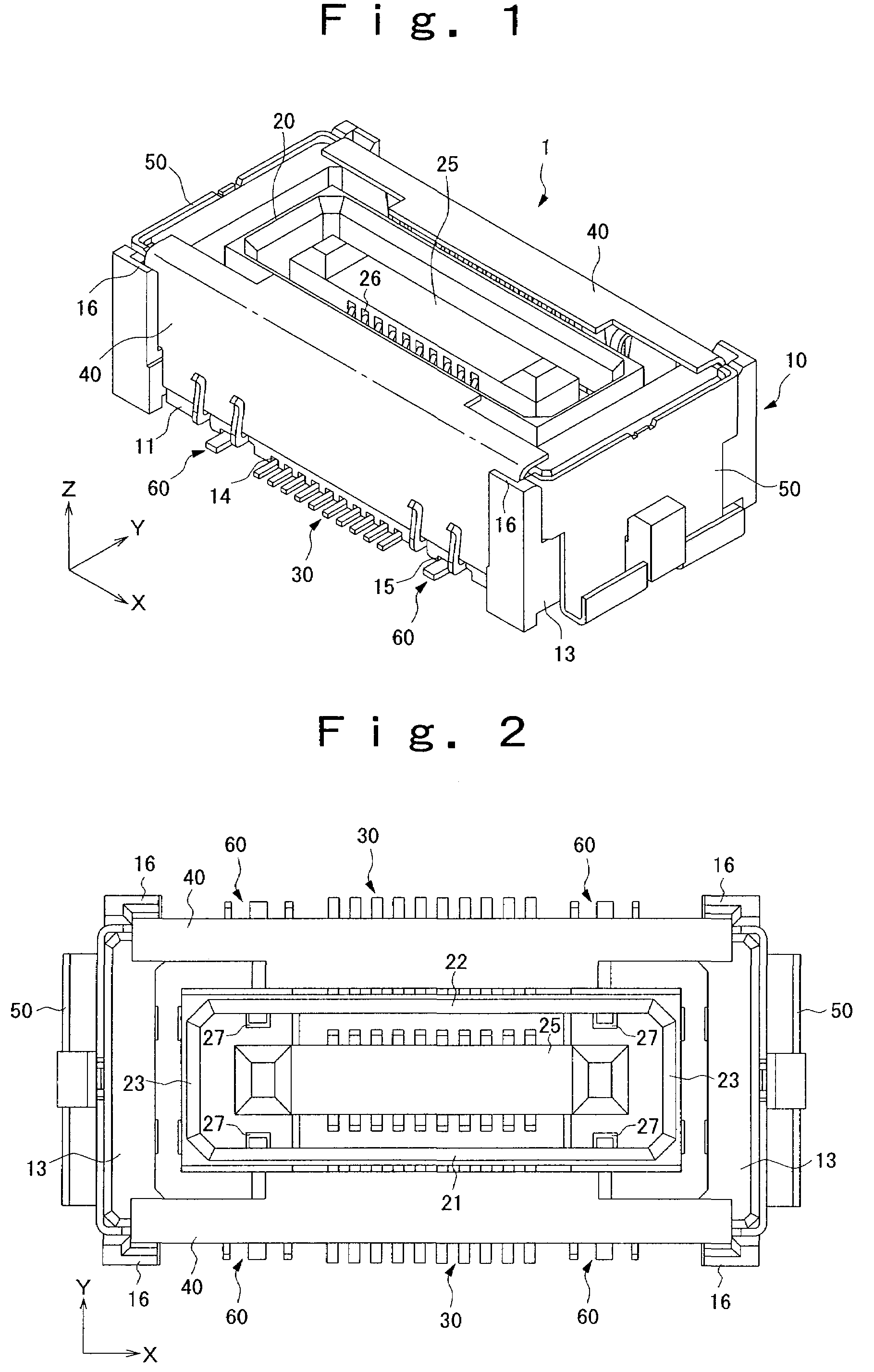
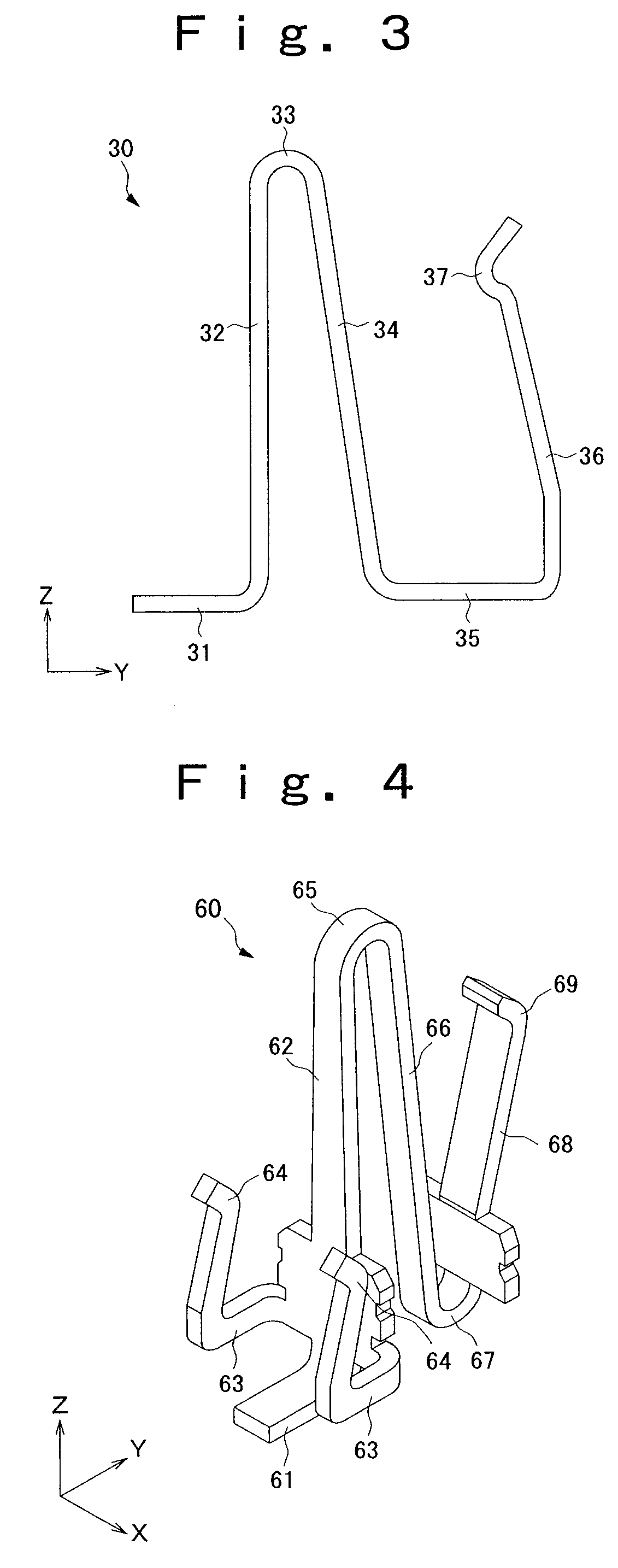
[0035]FIGS. 1 to 10 show an embodiment of the present invention. More specifically, FIG. 1 is a perspective view of a socket; FIG. 2 is a plan view of the socket; FIG. 3 is a side view of a socket terminal; FIG. 4 is a perspective view of a shield terminal; FIG. 5 is a side sectional view of the socket; FIG. 6 is a perspective view of a plug; FIG. 7 is a plan view of the plug; FIG. 8 is a side sectional view of the plug; and FIGS. 9 and 10 each is a side sectional view of an operation when the socket is mated with the plug.

[0036]The connector consists of a socket 1 serving as a first housing arranged on a first printed-circuit board 100 serving as one of objects to be connected; and a plug 2 serving as a second housing arranged on a second printed-circuit board 200 serving as the other object to be connected, is provided so as to be movable with respect to the socket 1, and is formed so as to be matable with the socket 1. The connector is used to electrically connect between the pri...


PUM


Abstract

The present invention provides a connector which can take an EMI measure for the first and second housings and can move the second housing with respect to the first housing. The connector comprises a plug which is provided so as to be movable with respect to the socket; a plurality of socket terminals which are resiliently deformed with a movement of the plug; a first socket side shield member which covers an outer circumference surface in the width direction of the socket; a plurality of plug terminals which are in contact with each of the socket terminals when the plug is mated with the socket; a plug side shield member which covers an outer circumference surface in the width direction of the plug; and first and second shield conductive portions which are in contact with each of the shield members and are resiliently deformed as the plug is moved.

Description

RELATED APPLICATIONS[0001]The present application is based on, and claims priority from, JP Application Number 2006-273953, filed Oct. 5, 2006, and PCT Application No. JP06 / 325400, filed Dec. 20, 2006, the disclosures of which are hereby incorporated by reference herein in their entireties.BACKGROUND OF THE INVENTION[0002]1. Field of the Invention[0003]The present invention relates to a connector which is attached to a printed-circuit board or the like and is used to electrically connect a plurality of printed-circuit boards to each other.[0004]2. Description of the Related Art[0005]Conventionally, as such a connector, there has been known a connector provided with a first housing which is provided at one connection object side; a second housing which is provided at the other connection object side and is formed so as to be matable with the first housing; a plurality of first terminals which are held by the first housing; a first shield member which is provided in the first housing ...

Claims


Application Information

Patent Timeline
Patent Type & Authority Patents(United States)
IPC IPC(8): H01R13/648
CPCH01R13/26H01R13/6583H01R13/6594H01R12/716H01R13/629H01R13/639H01R13/648
Inventor MATSUZAKI, SHINICHISUZUKI, HITOSHI
Owner IRISO ELECTRONICS CO LTD
Why Eureka
Try Eureka