Device connector with mating terminals bolted together

Active Publication Date: 2009-08-11
SUMITOMO WIRING SYST LTD
View PDF9 Cites 66 Cited by
  • Summary
  • Abstract
  • Description
  • Claims
  • Application Information

AI Technical Summary

Benefits of technology

[0010]According to such a construction, a bolt can be inserted into the fitting of the housing through the operation hole to fasten the bolt insertion holes of the first and second terminals arranged one over the other in the fitting. A strong connection is realized at a connected part of the first and second terminals in addition to the one at a connected part of the device-side terminal and the first terminal. Thus, connection reliability can be improved.
[0012]According to such a construction, the both terminals can be tightened with the bolt with the first and second shielding shells fixed. In other words, both terminals can be tightened with the bolt while the two housings are connected and relative displacements of the bolt insertion holes of the both terminals prevented. Therefore, the bolt tightening operation can be performed easily.
[0015]At least one of the bolt insertion holes of the first and second terminals may have a long shape in the connecting direction of the two housings. Then, the bolt insertion holes overlap even if the first and second terminals are displaced relative to each other in the fitting portion of the housings, provided that the displacement is within the length range of the bolt insertion hole. As a result, the two terminals can be tightened by the bolt.

Problems solved by technology

However, such strong connection is not realized at connected parts of the first terminals and the second terminals and, hence, there is a demand for further improving connection reliability.

Method used


Image

  • Device connector with mating terminals bolted together
  • Device connector with mating terminals bolted together
  • Device connector with mating terminals bolted together

Examples


Embodiment Construction

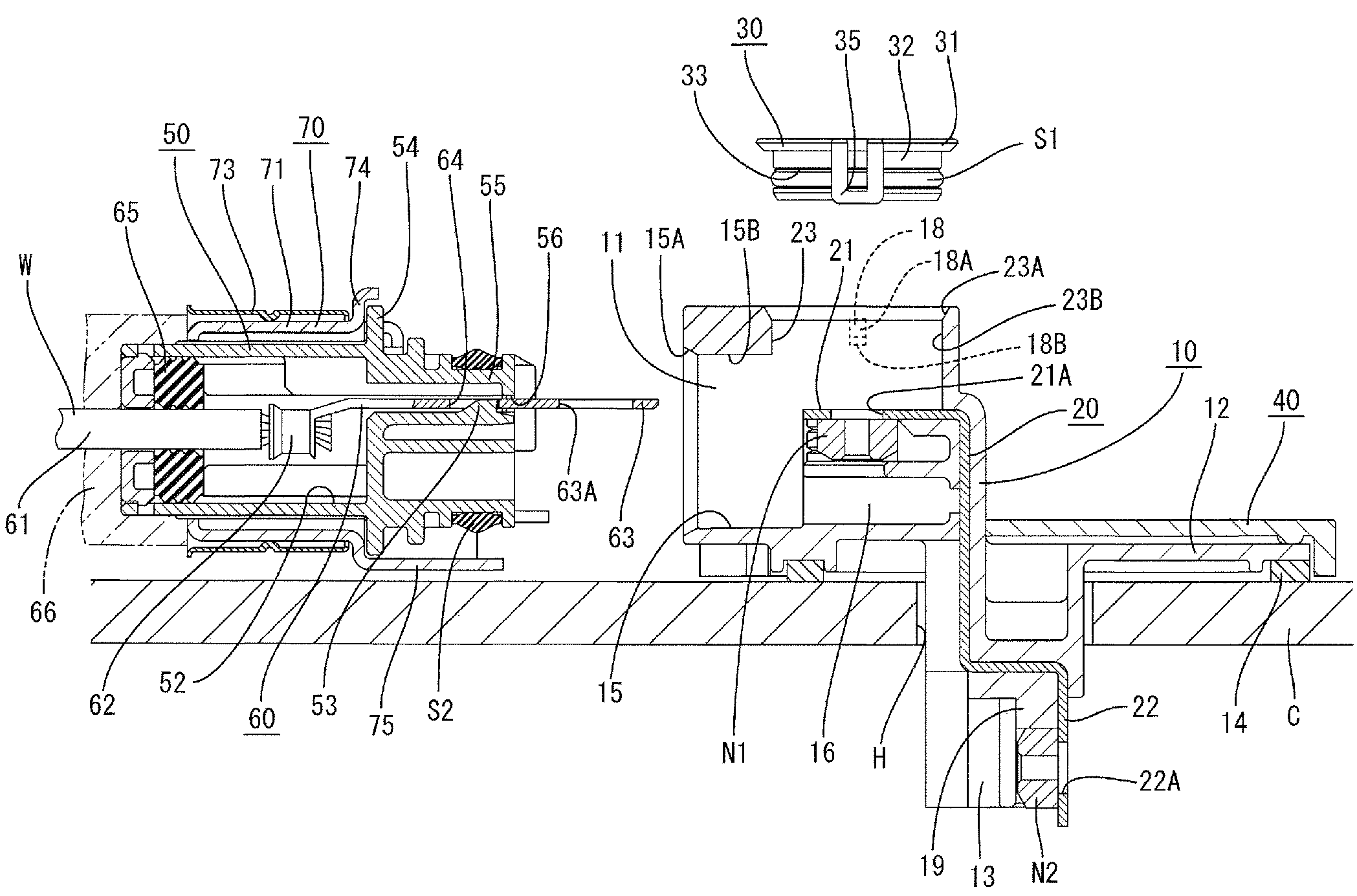
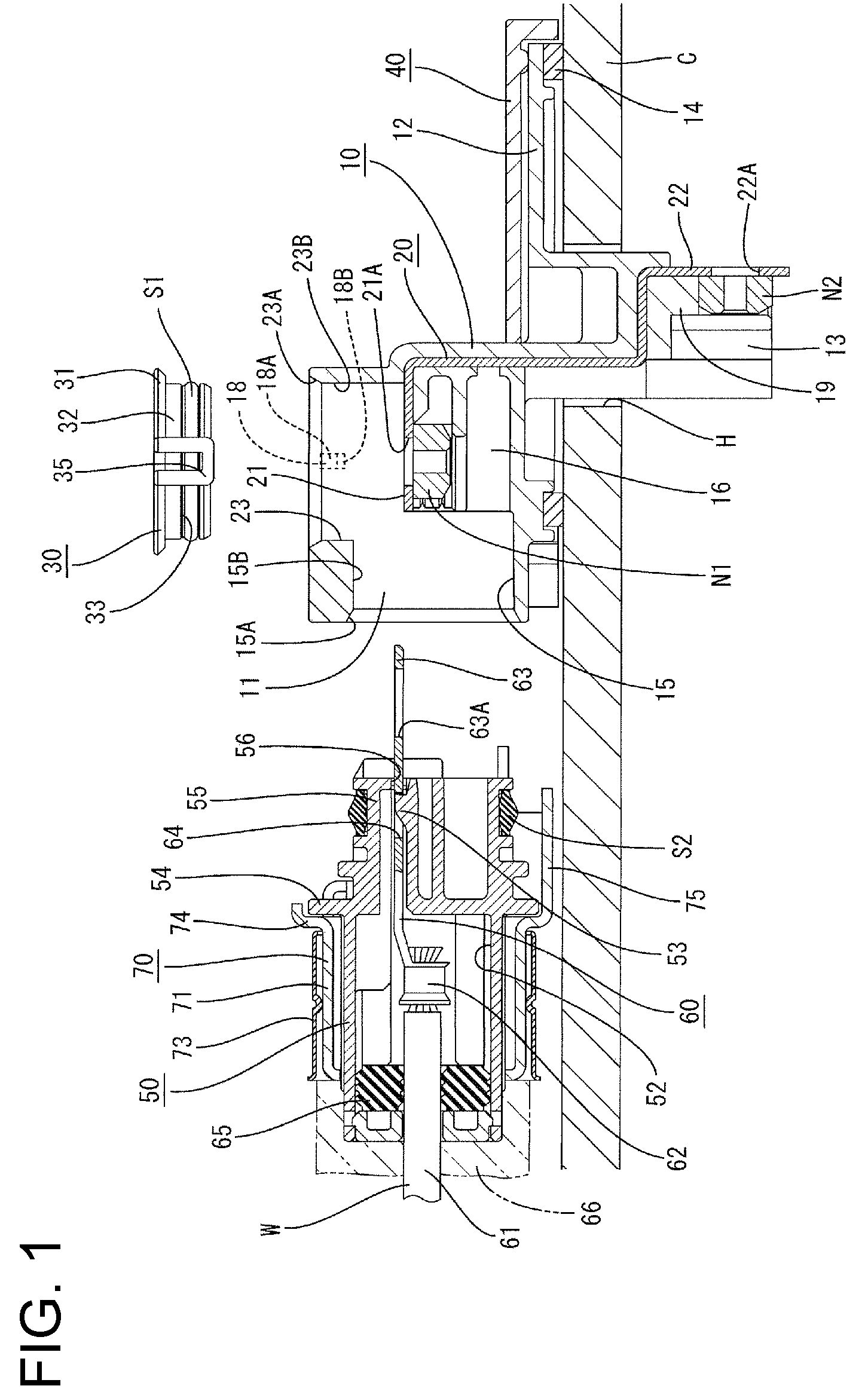
[0029]A device connector according to the invention is described with reference to FIGS. 1 to 10. The device connector is used for supplying power to an unillustrated device (e.g. a motor, an inverter or the like installed in a hybrid vehicle or the like) and has first and second housings 10 and 50 that are connectable with and separable from each other. In the following description, ends of the two housings 10, 50 to be connected are referred to as front ends, and reference is made to FIG. 1 concerning upper and lower sides. The device is to be accommodated in a conductive metal case C having a shielding function. The case C has a mount hole H that penetrates the case C substantially in inward and outward directions.

[0030]The first housing 10 is made e.g. of synthetic resin and includes a first fitting 11 in the form of a wide oblong parallelepiped. Flanges 12 extend back from opposite sides of the bottom end of the first fitting 11 and a device-side fitting 13 projects out and dow...


PUM


Abstract

A device connector to be connected with device-side terminals accommodated in a metal case (C) is provided with a first housing (10) for holding first terminals (20) connectable with the device-side terminals by bolt tightening and a second housing (50) connectable with the first housing (10) and adapted to hold second terminals (60) fixed to ends of wires (61). Connecting portions (21, 63) of the first and second terminals (20, 60) are arranged one over the other in a fitting (11) to the second housing (50) and are respectively formed with bolt insertion holes (21A, 63A). The fitting (11) is formed with an operation hole (23) used for bolt tightening operations for the connecting portions (21, 63).

Description

BACKGROUND OF THE INVENTION[0001]1. Field of the Invention[0002]The invention relates to a device connector for supplying power to a device accommodated in a metal case.[0003]2. Description of the Related Art[0004]Japanese Unexamined Patent Publication No. 2006-31962 discloses a device connector for supplying power to a device such as a motor accommodated in a metal case in an electric automotive vehicle or the like. This device connector is provided with a first housing to be mounted in a mount hole that penetrates the case in inward and outward directions and a second housing to be mounted on ends of wires. The two housings are connectable with each other.[0005]First terminals that are long and narrow in a connecting direction of the two housings are held in the first housing. Ends of the first terminals to be arranged at a side toward the device are formed with bolt holes and the first terminals are connected with device-side terminals by tightening bolts. Ends of the first termi...

Claims


Application Information

Patent Timeline
Patent Type & Authority Patents(United States)
IPC IPC(8): H01R24/00
CPCH01R13/207H01R13/4223H01R13/5205H01R13/5219H01R13/6215H01R13/648H01R13/5213H01R2201/26H01R13/46H01R13/512
Inventor MATSUOKA, HIROYUKI
Owner SUMITOMO WIRING SYST LTD
Why Eureka
Try Eureka