Optical sensor with chemically reactive surface

Active Publication Date: 2010-01-26
SPORIAN MICROSYST
View PDF19 Cites 53 Cited by
  • Summary
  • Abstract
  • Description
  • Claims
  • Application Information

AI Technical Summary

Problems solved by technology

Furthermore, many of the applications requiring such sensors are mobile or remote applications that do not have ready access to a power supply that is not a battery or other stored type of power supply.

Method used


Image

  • Optical sensor with chemically reactive surface
  • Optical sensor with chemically reactive surface
  • Optical sensor with chemically reactive surface

Examples


Embodiment Construction

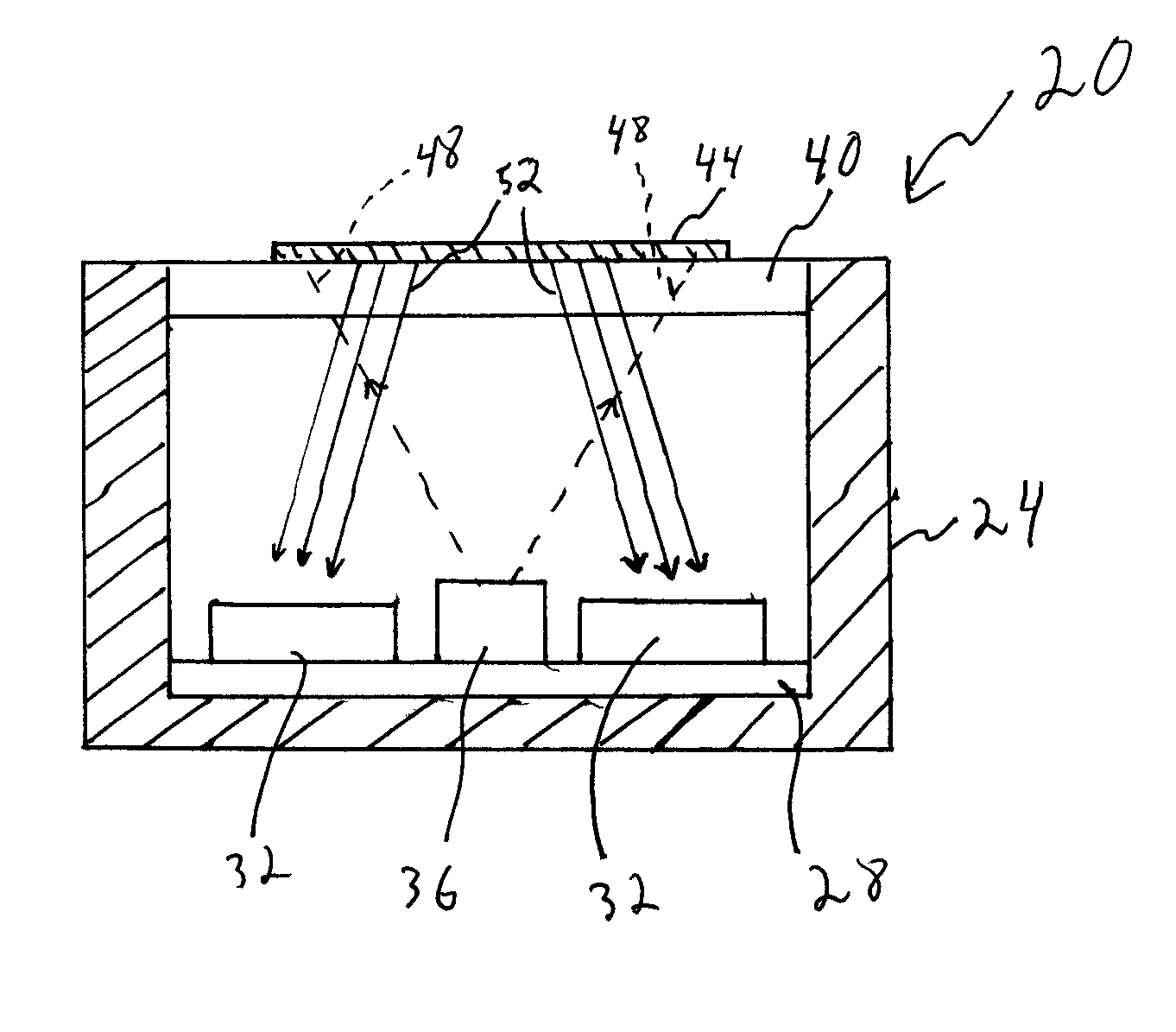
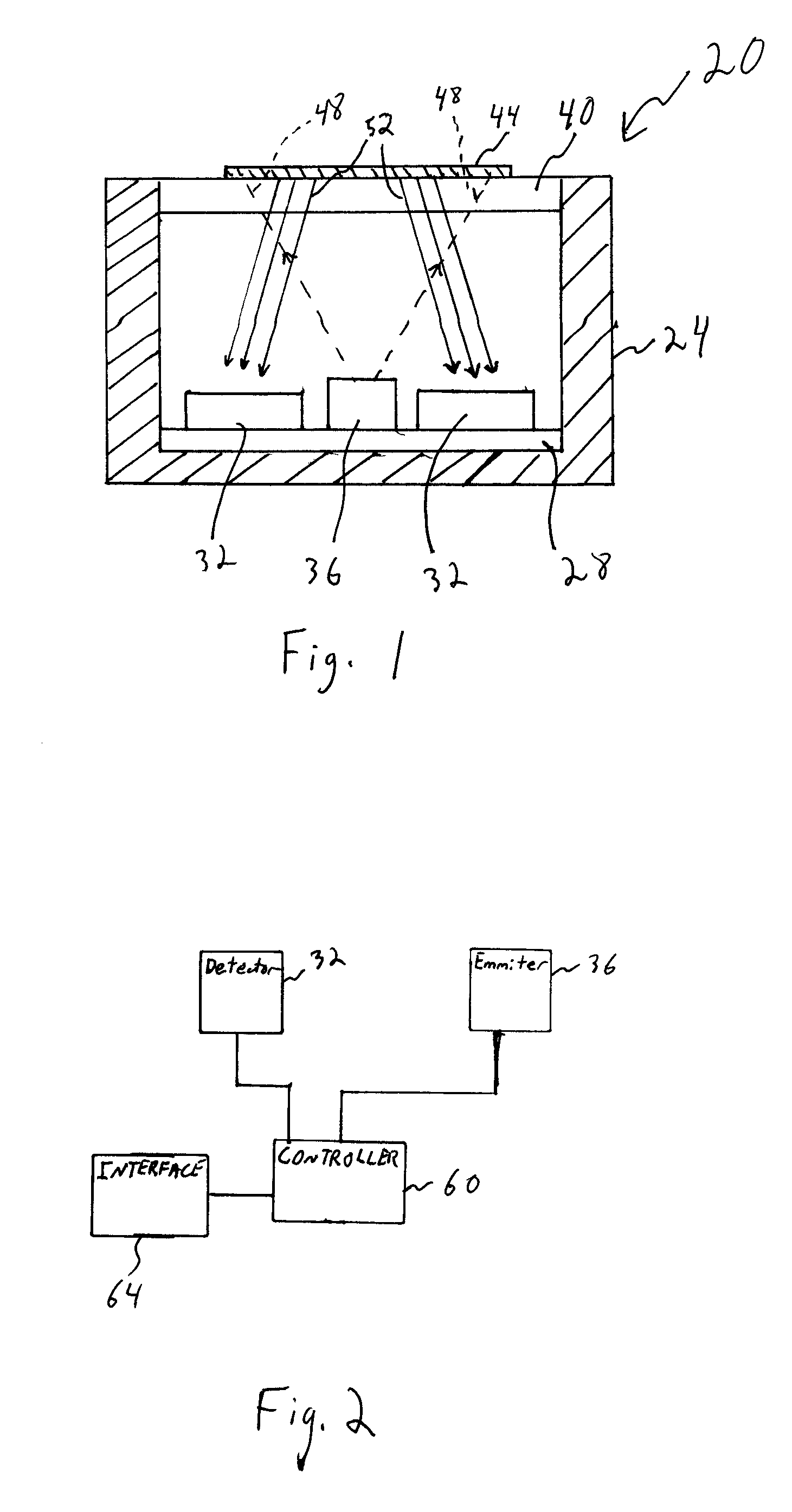
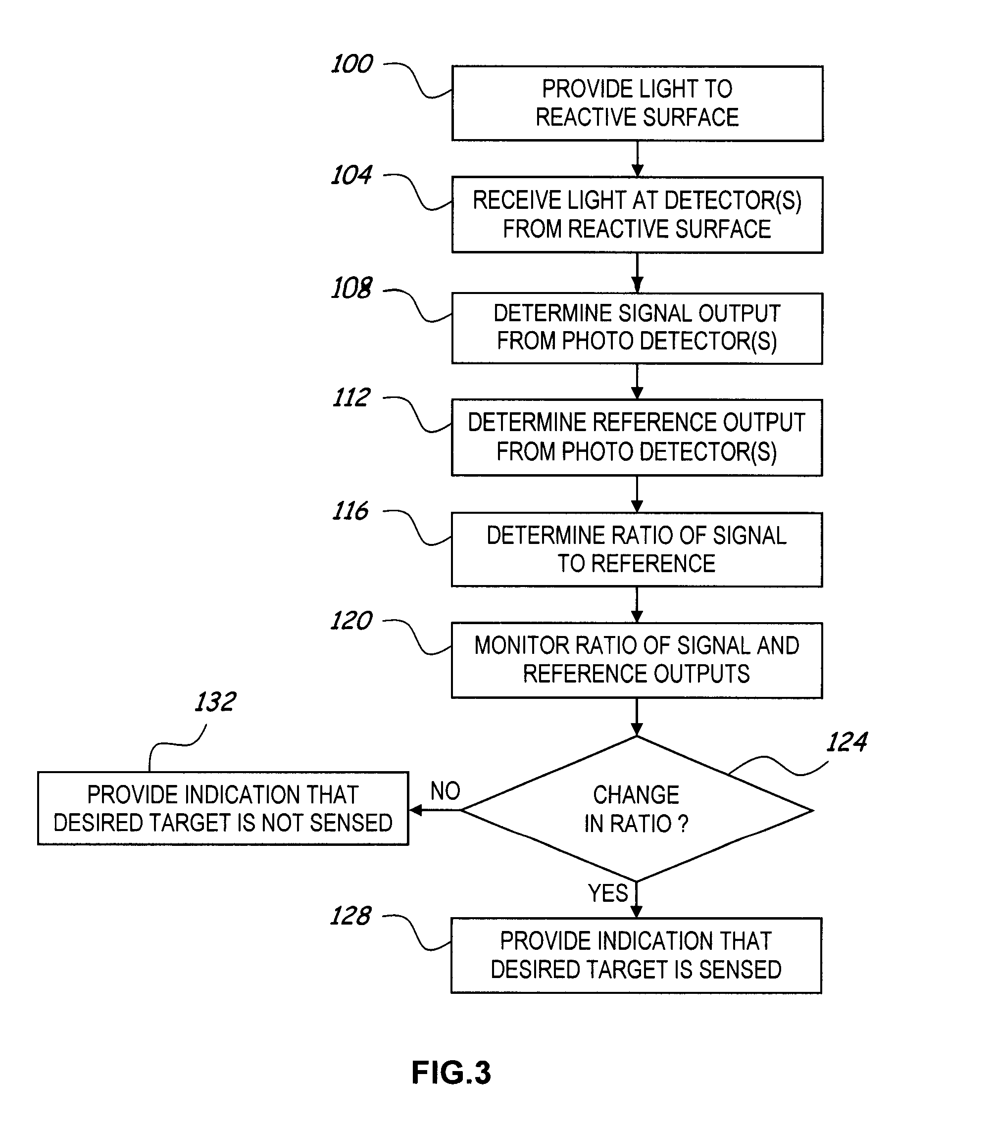
[0021]The present invention generally relates to an improved optical sensor and methods for measuring the presence of various materials or constituents in a fluid sample using a reactive material in the fluid sample that changes optical properties in the presence of the reactive material in the fluid sample. Optical sensors described herein use relatively little power and may also be used to sense an array of different parameters. The sensors of the various embodiments discussed herein rely on detecting a variation in intensity of light reflected onto one or more photo detectors from one or more interfaces in the optical path between an emitter and the photo detector(s). There are several general phenomena that result in intensity modulation at the photo detector(s). These phenomena in various embodiments are utilized sensor alone and / or in combination. A first general phenomena is an absorption change within the optical path, such as the amount of light absorbed by a sensitive mate...


PUM

PropertyMeasurementUnit
optical propertyaaaaaaaaaa
index of refractionaaaaaaaaaa
optical absorptionaaaaaaaaaa

Abstract

An improved optical sensor and methods for measuring the presence of various materials or constituents in a fluid sample uses reactive material(s) in a fluid environment. The reactive materials have optical properties that change in the presence of a target material that may be present in the environment. An optical emitter generates light that is directed to the reactive materials, and one or more optical detectors receive reflected light from one or more interfaces in the optical path between the emitter and the detector(s), one or more of the interfaces having a reactive material. The reactive material(s), emitter(s), and detector(s) are selected based on the desired target material to be sensed.

Description

STATEMENT REGARDING FEDERALLY SPONSORED RESEARCH OR DEVELOPMENT[0001]This invention was made with Government support under U.S. Army contract nos. DAAE30-02-C-1062, DAAE30-03-C-1075, W31P4Q-05-C-R100, and W31P4Q-06-C-0317. The Government may have certain rights to this invention.FIELD OF THE INVENTION[0002]The present invention generally relates to an optical sensor for sensing the presence of a chemical substance in a fluid sample. More specifically, the invention relates to measuring optical characteristics of a chemically reactive surface that is exposed to the fluid sample.BACKGROUND OF THE INVENTION[0003]Numerous applications require the determination of the presence or absence of one or more substances in a particular sample. In particular, several application require that the presence or absence of a material in a fluid sample be detected. Such applications include, for example, determining or monitoring of emissions from stationary or mobile sources for the presence of one o...

Claims


Application Information

Patent Timeline
Patent Type & Authority Patents(United States)
IPC IPC(8): G01N21/55
CPCG01J3/02G01J3/0208G01J3/0262G01J3/0291G01J3/44G01J3/443G01N21/274G01N21/6428
Inventor HARSH, KEVINSCHAIBLE, BRIANZHANG, WENGEGARRETT, WILLIAM
Owner SPORIAN MICROSYST
Why Eureka
Try Eureka