Rotary tool for friction stir spot welding and method of friction stir spot welding using the same

a technology of friction stir and spot welding, which is applied in the direction of manufacturing tools, soldering devices, auxillary welding devices, etc., can solve the problems of inability to repeat the friction stir spot welding operation, inability to detect the presence of gap between the probe and the shoulder member, and inability to achieve friction stir spot welding. , to achieve the effect of suppressing or preventing troubles, effectively suppressing the entry of plastically fluidized materials

Active Publication Date: 2010-02-02
SUMITOMO LIGHT METAL INDS LTD
View PDF16 Cites 14 Cited by
  • Summary
  • Abstract
  • Description
  • Claims
  • Application Information

AI Technical Summary

Benefits of technology

[0020]Accordingly, in the rotary tool for friction stir spot welding according to the present invention, the double-acting structure of the probe and the shoulder member is employed. Even though the gap is present between them, that is, between the outer peripheral surface of the probe and the inner peripheral surface of the shoulder member, the gap is formed to have a small gap on the tip portion side, and is formed to have an enlarged gap having larger clearance on the base portion side. Thereby, when a plastically fluidized material enters the gap between the probe and the shoulder member of the rotary tool from the friction stir region (joint portion) formed in the stacked portions formed by stacking the planar portions of the metal members to be joined, the presence of the small gap on the tip portion side can suppress the entry of the material, while the material that has once entered the gap is introduced into the enlarged gap with the large clearance. This can effectively suppress or prevent troubles caused by the adhesion and accretion of the material in the gap between the probe and the shoulder member.
[0021]In addition, the effects and advantages obtained by the employment of the above gap structure can also be obtained similarly, even when the gap formed between the inner peripheral surface of the pressing member and the outer peripheral surface of the shoulder member includes a combination of the small gap and enlarged gap in the rotary tool for friction stir spot welding having the double-acting structure in which the cylindrical pressing member is disposed outwardly of the shoulder member. Therefore, the presence of the small gap can effectively suppress the entry of the plastically fluidized material of the friction stir portion into the gap between the pressing member and the shoulder member. At the same time, due to the presence of the enlarged gap positioned behind the small gap, even if material flows into, it can be favorably introduced into the base portion side of the rotary tool, whereby troubles caused by material adhesion can effectively be alleviated or prevented.
[0022]In addition, according to the method of friction stir spot welding according to the above present invention, after performing friction stir spot welding operation using the rotary tool for friction stir spot welding according to the present invention, the probe and the shoulder member and / or the shoulder member and the pressing member are repeatedly inserted and extracted so as to be moved axially relatively to each other. This can effectively facilitate ejection of material debris of the metal members to be joined that are flown into the gap between the probe and shoulder member and / or the gap between the shoulder member and the pressing member from the friction stir region of the stacked portions formed therein and accumulated or adhered thereto. This allows smooth friction stir spot welding operation and can more favorably increase a repeatable frequency that permits continuous friction stir spot welding operation.

Problems solved by technology

The left hole has caused problems such as liquid accumulation at a time of coating or has internally had a problem of adverse effect on joint strength (strength of a junction) between the metal plate members to be joined.
However, due to the double-acting structure of the employed rotary tool, the presence of a clearance (gap) is inevitable between the probe and the shoulder member.
This causes intrinsic problems in which the probe and the shoulder member have difficulty in operating (moving) independently of each other and thereby repetition of friction stir spot welding operation becomes impossible.

Method used


Image

  • Rotary tool for friction stir spot welding and method of friction stir spot welding using the same
  • Rotary tool for friction stir spot welding and method of friction stir spot welding using the same
  • Rotary tool for friction stir spot welding and method of friction stir spot welding using the same

Examples


example 1

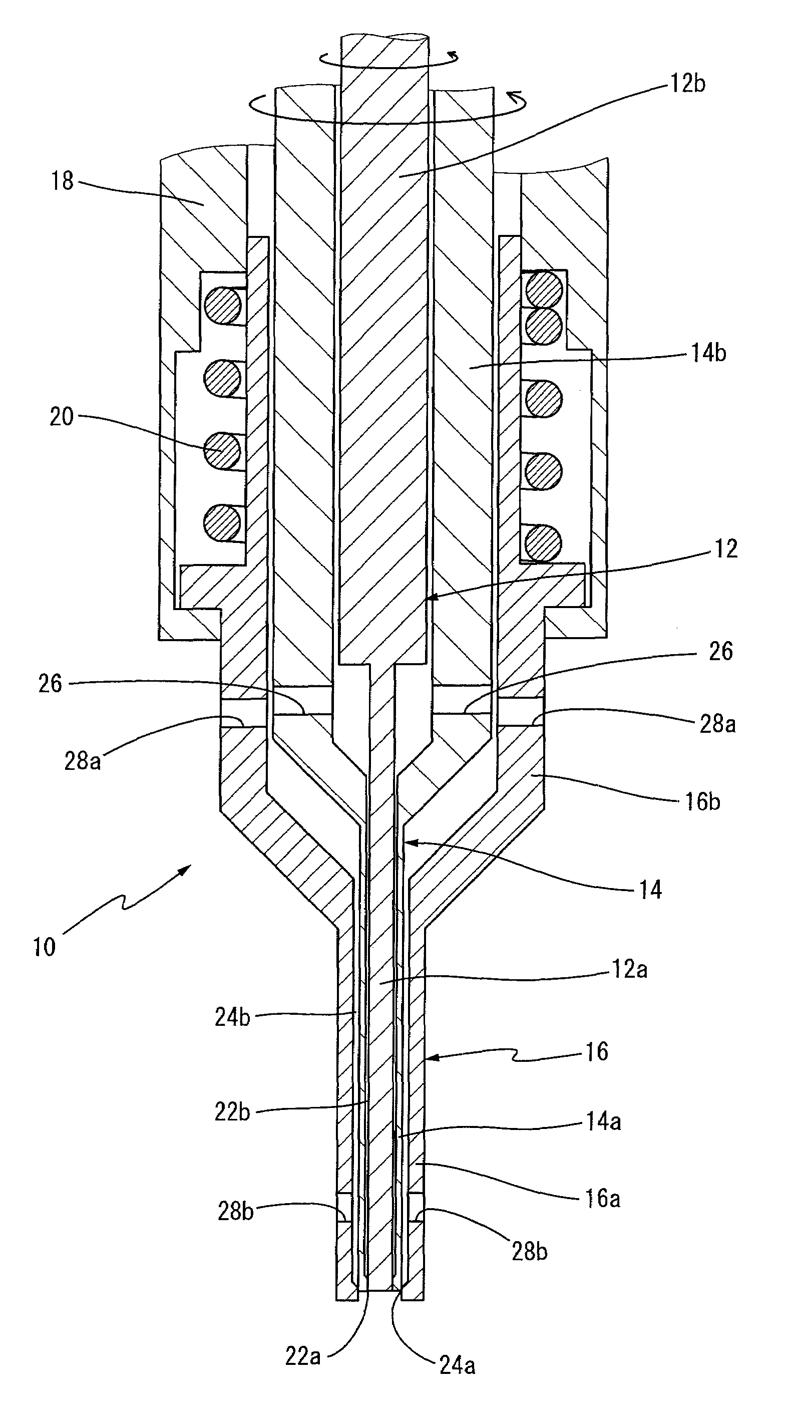
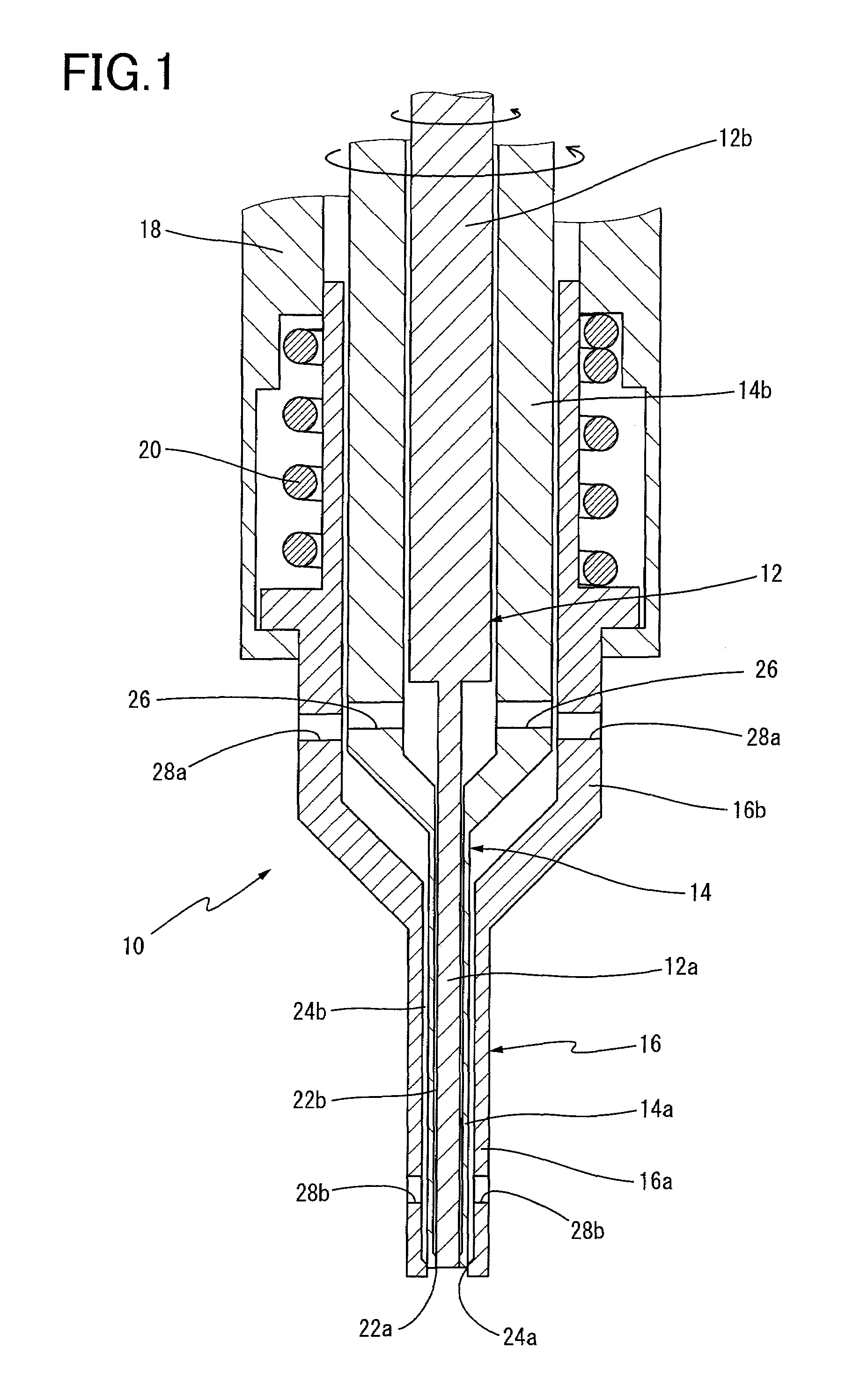
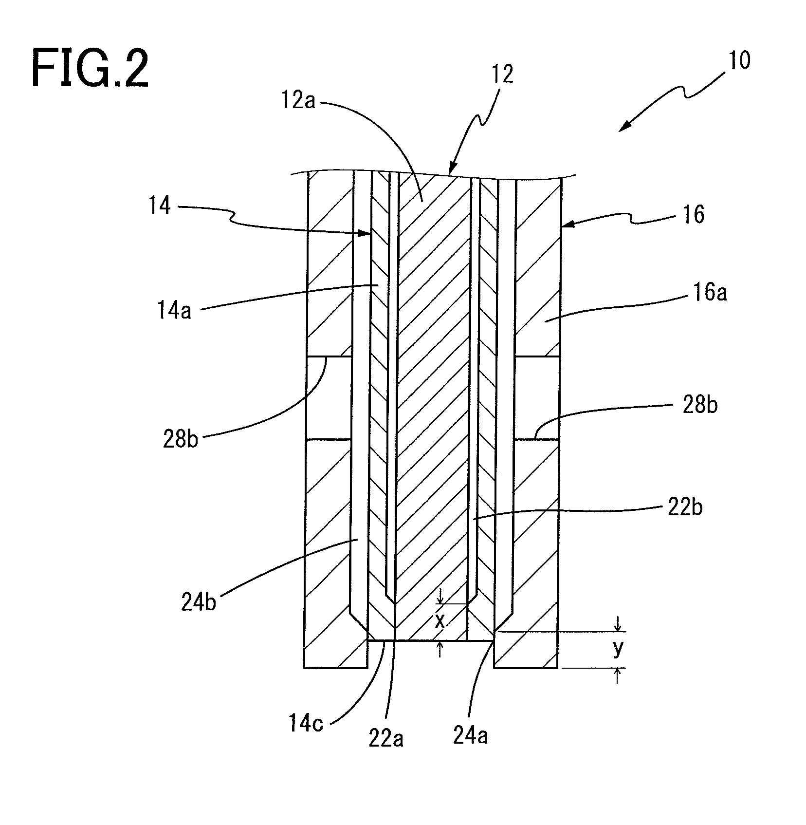
[0077]First, two sheets of plates were prepared as metal members to be joined. Each of them was made of a 6000-series aluminum plate material (6016-T4) with a thickness of 1 mm. In addition, the rotary tool 10 having the double-acting structure shown in FIG. 1 and FIG. 2 was prepared that has the small gaps 22a and 24a with respective axial lengths x and y of 5 mm.

[0078]Next, the two aluminum plate members were stacked on each other, and in a state in which the backing jig 30 was abutted against a lower plate, the friction stir spot welding was performed as shown in FIG. 3 and FIG. 4. Specifically, after the pressing member 16 of the rotary tool 10 was abutted against an upper plate side, the probe 12 and the shoulder member 14 being rotated at a high speed were abutted so as to be flush with one another. Next, the probe 12 was inserted into the plates so as to reach up to ⅓ of a thickness of the lower plate to form the friction stir region 36. After that, when retracting the probe ...


PUM

PropertyMeasurementUnit
lengthaaaaaaaaaa
axial lengthsaaaaaaaaaa

Abstract

A rotary tool for friction stir spot welding including: a rod-like probe to be inserted into one side of stacked planar portions of plural metal members to be joined while being rotated; and a cylindrical shoulder member which is disposed coaxially outwardly of the probe and which has a shoulder surface to be abutted against the one side of the stacked portions while being rotated, wherein the probe and the shoulder member are individual components and are disposed so as to have a double-acting structure which enable them to move independently in their axial direction, and in which a gap between an inner surface of the shoulder member and an outer surface of the probe is formed to have a small gap on a tip side of the rotary tool and to have an enlarged gap having larger clearance than the small gap on a base portion side thereof.

Description

[0001]This application is a continuation of the International Application No. PCT / JP2006 / 308092, filed Apr. 18, 2006, which claims the benefit under 35 U.S.C. § 119(a)-(d) of Japanese Application 2005-121088, filed Apr. 19, 2005, the entireties of which are incorporated herein by reference.TECHNICAL FIELD[0002]The present invention relates to a rotary tool for friction stir spot welding and a method of friction stir spot welding using the same, and in particularly to a rotary tool for friction stir spot welding having a double-acting structure in which a probe and a shoulder member are individually formed, rotatable around their axes and movable axially independently of each other, as well as an effective method for smoothly continuing a friction stir spot welding operation by using the rotary tool.BACKGROUND ART[0003]Conventionally, in an automobile manufacturing process, body members and various components of the automobile have been manufactured by stacking a plurality of metal p...

Claims


Application Information

Patent Timeline
Patent Type & Authority Patents(United States)
IPC IPC(8): B23K20/12B23K37/00
CPCB23K20/125B23K20/1265
Inventor KUMAGAI, MASAKIAOKI, KENTA
Owner SUMITOMO LIGHT METAL INDS LTD
Why Eureka
Try Eureka