Crimp terminal having a groove for facilitating crimping workability and a water stop member

a technology of crimping terminal and groove, which is applied in the direction of connection contact member material, line/current collector details, and connections effected by permanent deformation, etc., can solve the problem of not being able to achieve the desired crimping form of electric wire, and achieve excellent crimping workability

Active Publication Date: 2020-09-01
YAZAKI CORP
View PDF27 Cites 0 Cited by
  • Summary
  • Abstract
  • Description
  • Claims
  • Application Information

AI Technical Summary

Benefits of technology

[0005]It is therefore an object of the present invention to provide a crimp terminal having excellent crimping workability.
[0009]According to still another aspect of the present invention, it is preferable that the crimp terminal further includes a water stop member that is overlaid on and attached to at least the groove portion in the inner wall surface of the electric wire connection portion before the crimping process is performed, and is filled in the groove portion by the crimping process and left therein, so as to suppress entry of water into the electric wire connection portion after the crimping process is completed.

Problems solved by technology

Thus, although the barrel piece in the electric wire connection portion is bent following the shape of a die on the free end side during a crimping process in general, the barrel piece is not bent following the shape of the die due to its rigidity, and there is a possibility that a desired crimping form for the electric wire cannot be achieved.

Method used


Image

  • Crimp terminal having a groove for facilitating crimping workability and a water stop member
  • Crimp terminal having a groove for facilitating crimping workability and a water stop member
  • Crimp terminal having a groove for facilitating crimping workability and a water stop member

Examples


embodiment

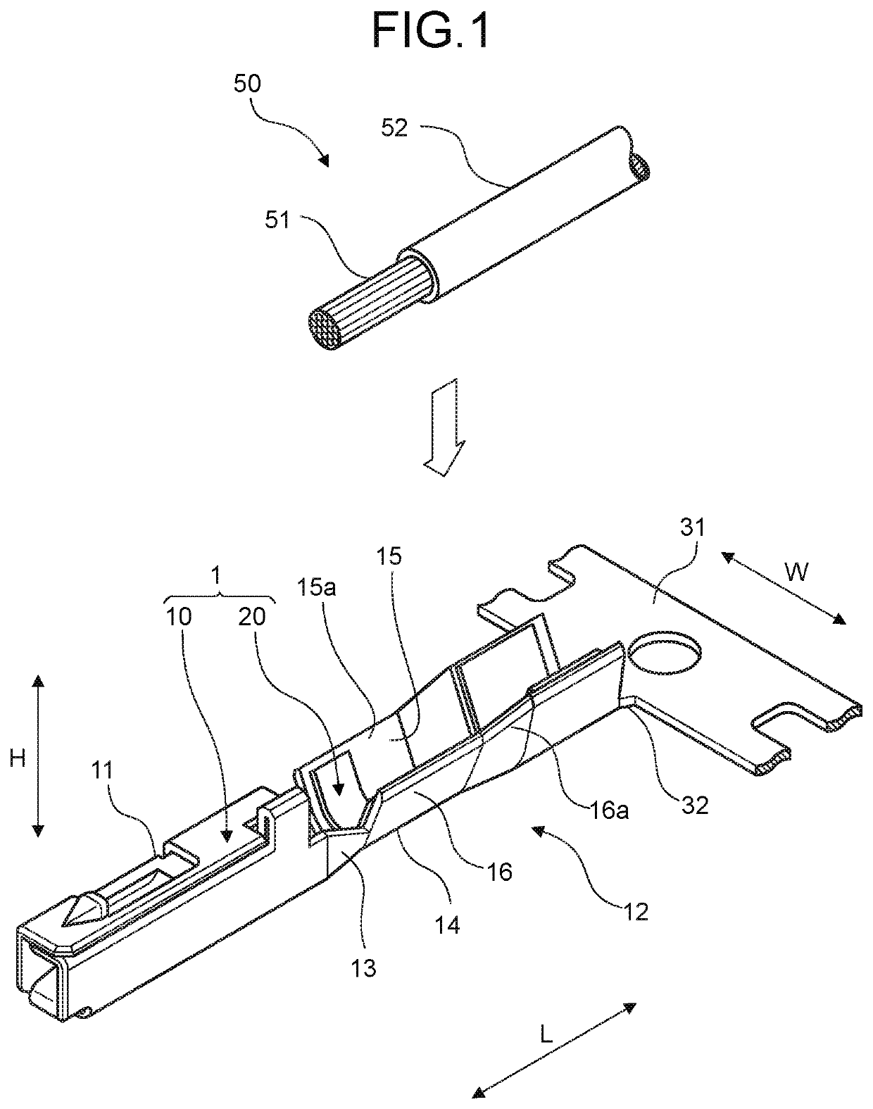
[0026]A crimp terminal according to one embodiment of the present invention is described with reference to FIG. 1 to FIG. 14.

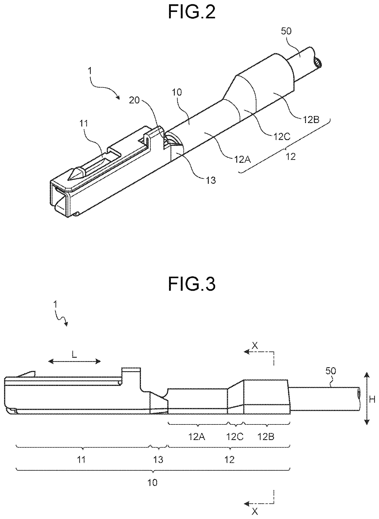
[0027]Reference numeral 1 in FIG. 1 to FIG. 3 represents a crimp terminal in the present embodiment. The crimp terminal 1 is electrically connected to an electric wire 50, and is electrically connected to a counterpart terminal (not shown) while being integrated with the electric wire 50. In this case, in order to expose a predetermined length of a core 51 at an end portion of the electric wire 50, a coating 52 is peeled off and removed by the length. The core 51 may be either an assembly of wires or a single wire like a coaxial cable. The crimp terminal 1 is crimped to the end portion of the electric wire 50 in order to be electrically connected to the electric wire 50, thereby being electrically connected to the exposed tip core (hereinafter referred to simply as “tip core”) 51.

[0028]The crimp terminal 1 in the present embodiment is exemplified as a crimp te...


PUM

PropertyMeasurementUnit
rigidityaaaaaaaaaa
pressure-sensitiveaaaaaaaaaa
electricallyaaaaaaaaaa

Abstract

A crimp terminal includes a terminal connection portion electrically connected to a counterpart terminal; and a plate-shaped electric wire connection portion electrically connected to an end portion of an electric wire placed on an inner wall surface side by a crimping process during which the electric wire connection portion is sandwiched between a first die and a second die. The electric wire connection portion includes a bottom on which the end portion of the electric wire is placed in the crimping process, and first and second barrel pieces that are extended from both ends of the bottom and are rolled to a region from a tip core to a coating at an end portion of the electric wire by the crimping process.

Description

CROSS-REFERENCE TO RELATED APPLICATION(S)[0001]This application is a continuation application of International Application PCT / JP2016 / 086252, filed on Dec. 6, 2016, and designating the U.S., the entire contents of which are incorporated herein by reference.BACKGROUND OF THE INVENTION1. Field of the Invention[0002]The present invention relates to a crimp terminal.2. Description of the Related Art[0003]Conventionally, crimp terminals including an electric wire connection portion to be electrically connected to a core of an electric wire have been known. The crimp terminal is formed by subjecting a metal plate serving as base material to punching, bending, and the like. The electric wire connection portion is a U-shaped portion formed from a bottom and two opposed barrel pieces, and in a crimping process, the bottom and free ends of the barrel pieces are sandwiched by two dice, an interval between the dice is decreased, and each of the barrel pieces is bent toward the other barrel piec...

Claims


Application Information

Patent Timeline
Patent Type & Authority Patents(United States)
IPC IPC(8): H01R4/18H01R43/048H01R43/00H01R13/52H01R4/70H01R4/62
CPCH01R4/184H01R43/005H01R13/52H01R4/70H01R4/62H01R43/048
Inventor IWATA, MASASHI
Owner YAZAKI CORP
Why Eureka
Try Eureka