
In-vehicle fuel cell stack

a fuel cell and stack technology, applied in the field of in-vehicle fuel cell stack, can solve the problems that foreign matter other than the air such as water, dust, mud, pebbles, etc., and may enter the stack case undetected

Active Publication Date: 2020-09-15
HONDA MOTOR CO LTD
View PDF8 Cites 0 Cited by
  • Summary
  • Abstract
  • Description
  • Claims
  • Application Information

AI Technical Summary

Benefits of technology

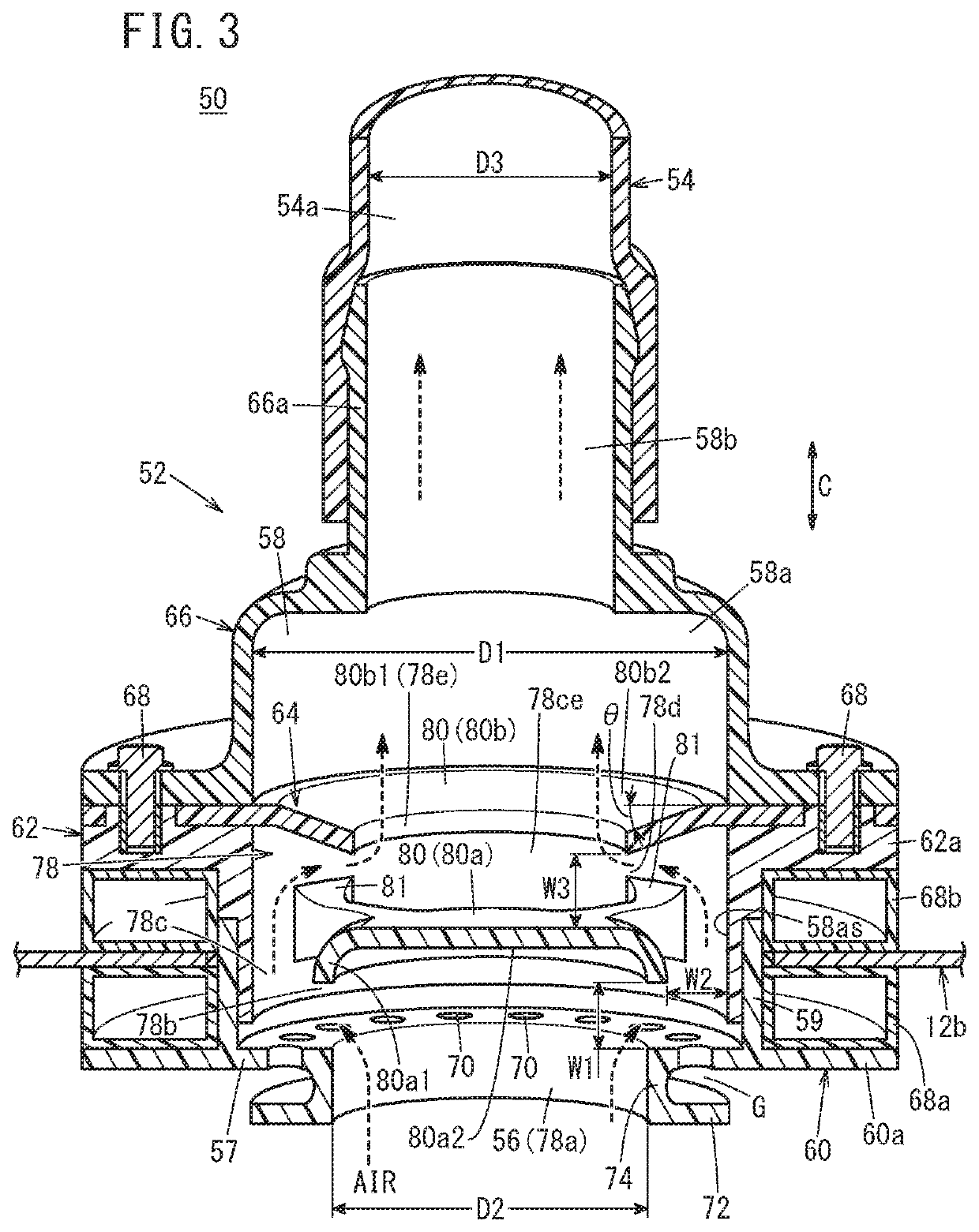
The present invention aims to provide an in-vehicle fuel cell stack that can prevent foreign matters such as water, dust, mud, pebbles, etc. from entering the stack case through the ventilation opening. This is achieved through the use of a labyrinth channel which prevents such foreign materials from entering the stack case and maintains the hydrogen gas concentration in the stack case within a certain level. The invention prevents the entry of foreign matters into the fuel cell stack, which can prolong the life of the stack and ensure its performance in a more stable manner.

Problems solved by technology

In the structure, there is a possibility that foreign matters other than the air such as water, dust, mud, pebbles may enter the stack case undesirably from the outside, through the air inlet port and the channel.

Method used


Image

  • In-vehicle fuel cell stack
  • In-vehicle fuel cell stack
  • In-vehicle fuel cell stack

Examples


Embodiment Construction

[0026]Hereinafter, a preferred embodiment of an in-vehicle fuel cell stack according to the present invention will be described with reference to the accompanying drawings.

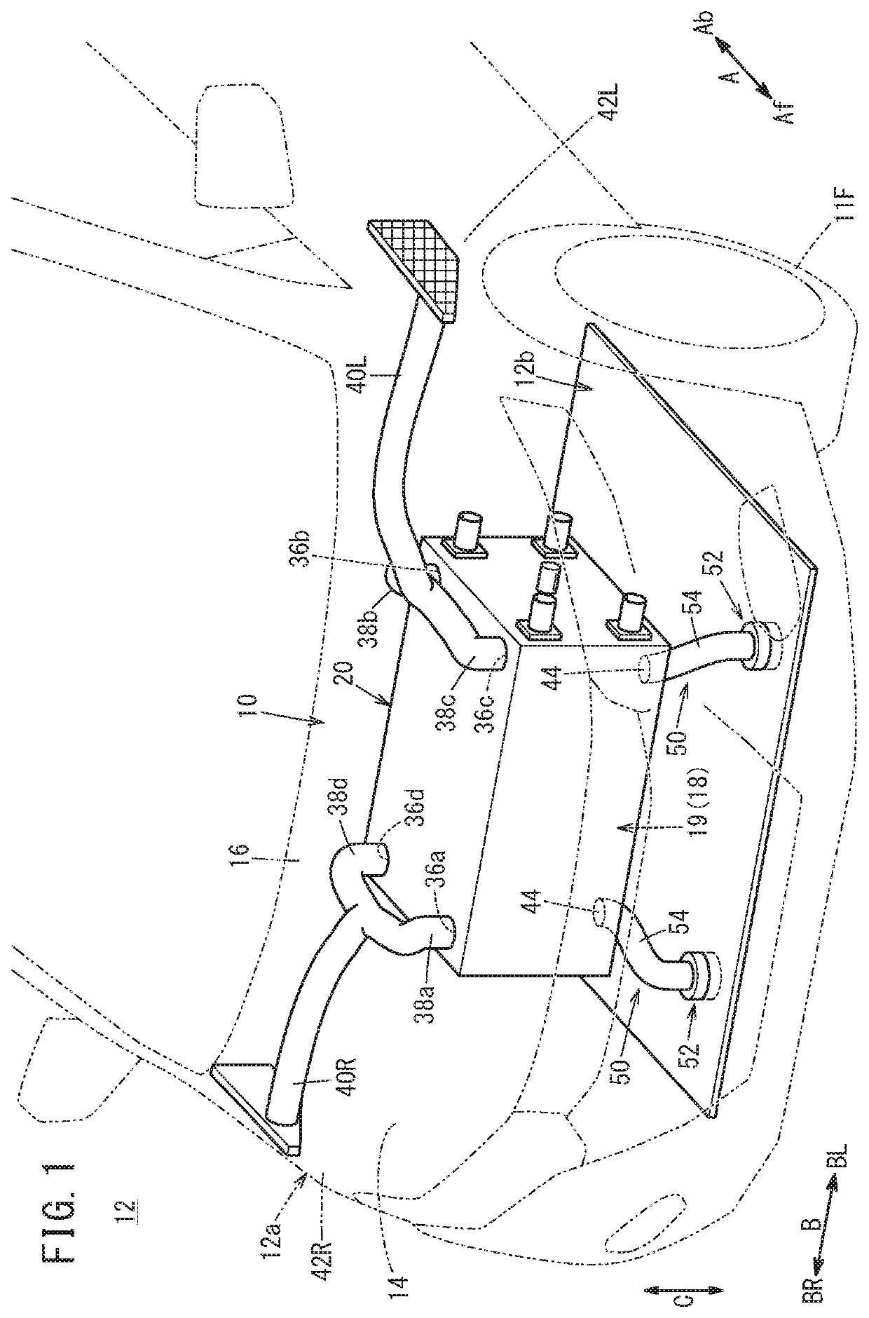
[0027]As shown in FIG. 1, the in-vehicle fuel cell stack 10 (hereafter referred to as the “fuel cell stack 10”) according to the embodiment of the present invention is mounted in a fuel cell vehicle 12 such as a fuel cell electric vehicle. The fuel cell vehicle 12 includes a vehicle body 12a including front wheels 11F and rear wheels (not shown).

[0028]A front box (motor room) 14 in which the fuel cell stack 10 is mounted is formed on the front wheels 11F side of the vehicle body 12a, ahead of the dashboard 16. It should be noted that the fuel cell stack 10 may not be mounted in the front box 14. For example, the fuel cell stack 10 may be mounted under the floor, or under the trunk lid.

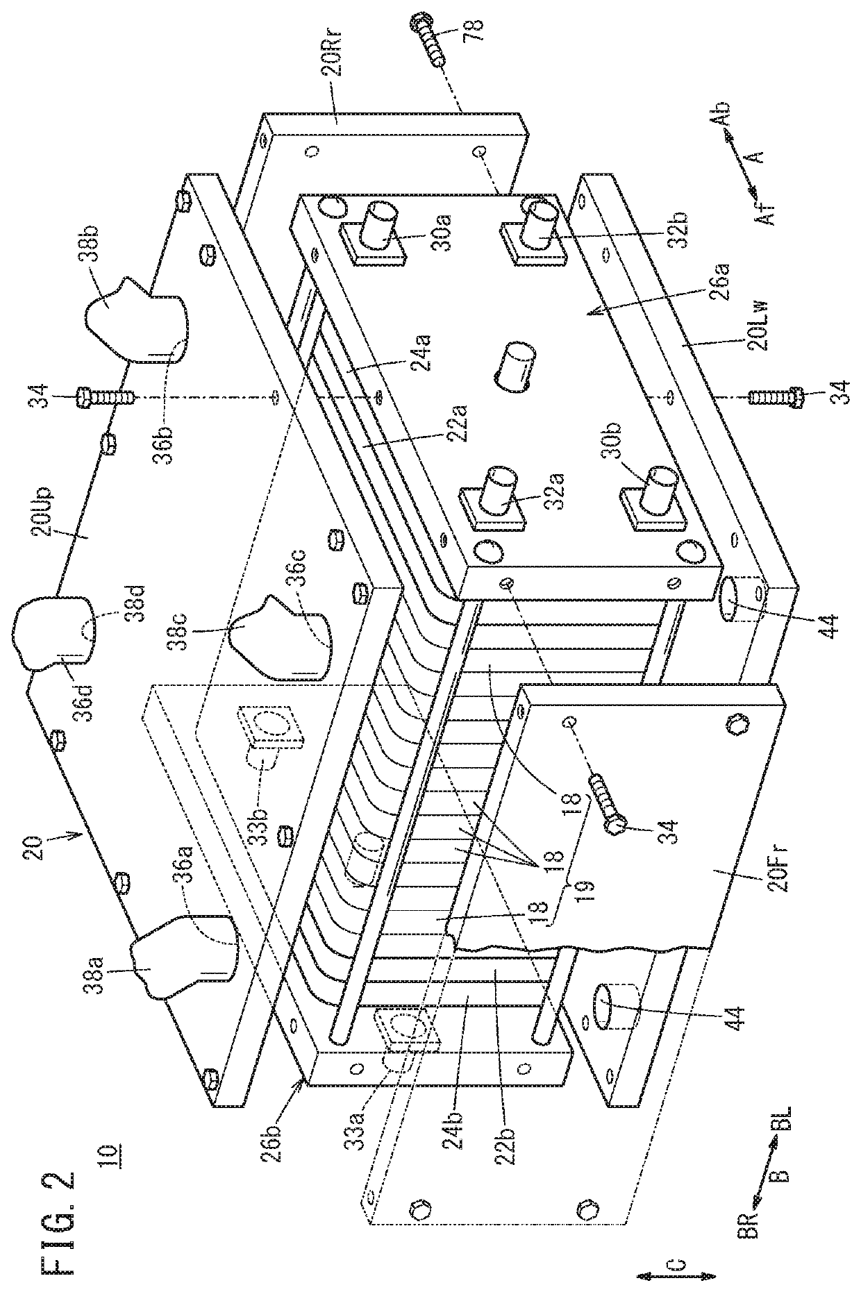
[0029]As shown in FIG. 2, the fuel cell stack 10 includes a stack body 19 formed by stacking a plurality of power generation cells ...


PUM

PropertyMeasurementUnit
electrical energyaaaaaaaaaa
gravityaaaaaaaaaa
lengthaaaaaaaaaa

Abstract

An in-vehicle fuel cell stack includes a ventilation mechanism for ventilating a stack case through a ventilation opening opened to the inside of the stack case. The ventilation mechanism includes an inlet member. An air inlet port and an inner channel are formed in the inlet member. A ventilating air is guided into the ventilation mechanism through the air inlet port. The inner channel connects the air inlet port and the ventilation opening. The inner channel includes a labyrinth channel.

Description

CROSS-REFERENCE TO RELATED APPLICATION[0001]This application is based upon and claims the benefit of priority from Japanese Patent Application No. 2016-224146 filed on Nov. 17, 2016, the contents of which are incorporated herein by reference.BACKGROUND OF THE INVENTIONField of the Invention[0002]The present invention relates to an in-vehicle fuel cell stack including a stack body formed by stacking a plurality of power generation cells in a stacking case, and a ventilation mechanism for ventilating the stack case.Description of the Related Art[0003]For example, a solid polymer electrolyte fuel cell includes a membrane electrode assembly (MEA). An anode is provided on one surface of an electrolyte membrane, and a cathode is provided on the other surface of the electrolyte membrane to form the membrane electrode assembly. The electrolyte membrane is a polymer ion exchange membrane. The membrane electrode assembly is sandwiched between separators to form a power generation cell (unit c...

Claims


Application Information

Patent Timeline
Patent Type & Authority Patents(United States)
IPC IPC(8): H01M8/04089H01M8/0662H01M8/02H01M8/2475H01M8/2484H01M8/241B60L50/72
CPCH01M8/241B60L50/72H01M8/0662H01M8/04089H01M8/02H01M8/2484H01M8/2475Y02T90/40H01M2250/20H01M8/04798H01M8/2465Y02E60/50Y02T90/16
Inventor SATO, MASAHIKO
Owner HONDA MOTOR CO LTD
Learn More