Non-contacting face seals and thrust bearings

Inactive Publication Date: 2010-02-02
CROSS MFG
View PDF51 Cites 6 Cited by
  • Summary
  • Abstract
  • Description
  • Claims
  • Application Information

AI Technical Summary

Benefits of technology

[0006]Embodiments of the present invention can improve the seal performance in terms of gas leakage rates and help to eliminate the additional weight and complexity resulting from the need to provide a separate gas supply to maintain the aerostatic gas film between the static and rotating members of the seal assembly. (In relatively rotating members, the slower member fulfills the role of the static member). This can be achieved by providing a series of wedged-shaped gas paths round the sealing annulus. The gas adjacent to the rotating member normally experiences a friction-generated drag effect and is drawn into the wedge-shaped spaces and so compressed before passing through the narrowest gaps between the stator and rotor members and thence

Problems solved by technology

The environment surrounding such engines is too hot to a

Method used


Image

  • Non-contacting face seals and thrust bearings
  • Non-contacting face seals and thrust bearings
  • Non-contacting face seals and thrust bearings

Examples


Embodiment Construction

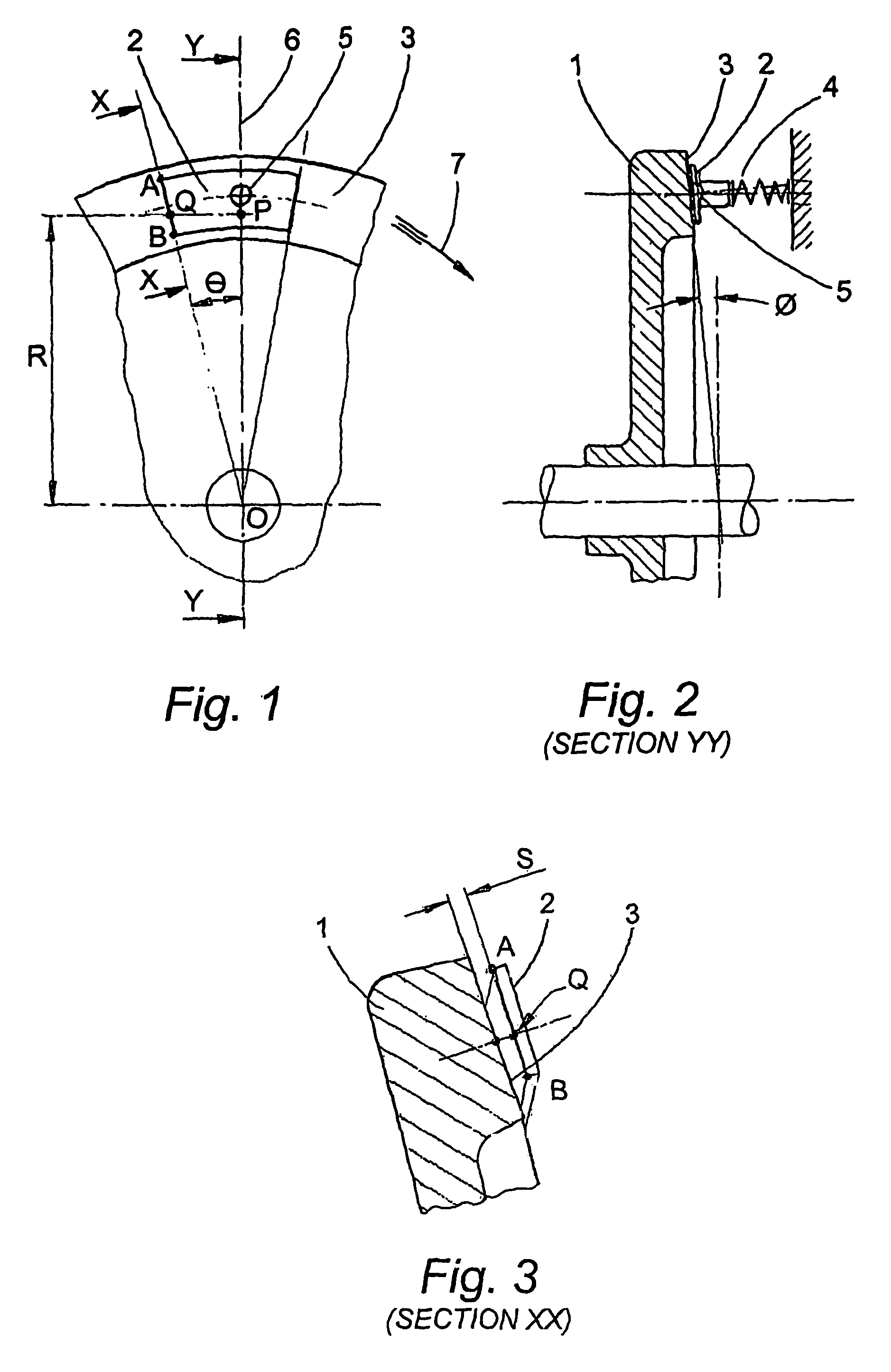
[0053]Referring to FIGS. 1 and 2, the rotating member 1 and tile 2 are shown in simplified form, the tile being urged against the conical surface 3 of the rotating member by the spring member 4. The side of the tile remote from the conical surface is provided with a spherical seated pivot centre or fulcrum 5 such that, with the rotating member 1 stationary, the spring member 4 will cause the tile 2 to make line contact with the conical surface 3, the line being in the same radial plane indicated by axis 6 in FIG. 1.

[0054]The cone angle Ø in FIG. 2 is defined as the angle that a line on the cone surface passing through the cone apex makes with an axis, which is at right angles to the rotation axis. The angle Ø is very small, typically within the range 0.3 to 1.0 degrees; but has been illustrated larger in FIG. 2 and subsequent figures for reasons of clarity.

[0055]With the rotation of member 1 as indicated by the arrow 7 in FIG. 1 the radial edge AB of the tile is designated the “lead...


PUM


Abstract

The apparatus, which can be used in aspirating face seals or thrust bearings, spaces two relatively rotatable facing surfaces in use by entraining gas between the surfaces. The apparatus includes a first portion (1) defining a generally frusto-conical surface (3); a second portion (2) defining at least one flat surface disposed adjacent the first portion so that the two surfaces face each other and define at least one point of closest engagement between the surfaces, with diverging gaps extending between the surfaces on either side of a plane which contains the point or points of closest engagement and which extends generally orthogonal to the direction of relative rotation, and a device (4) for biasing the flat surface towards the frusto-conical surface to maintain the gaps within a predetermined dimensional range.

Description

FIELD OF THE INVENTION[0001]Self aspirating seals can be used for partial sealing against the leakage of gases between the rotating and static assemblies of an engine. The sealing members are prevented from coming into physical contact by the inter-position of a pressurised film of gas, the pressure being self generated by the relative rotational velocity between the sealing members.[0002]In an alternative field of operation a similar self-generated gas pressure may be used to react between the rotating and static members to provide the axial reaction force in a thrust bearing application.BACKGROUND OF THE INVENTION[0003]It will be appreciated that the self-generated gas pressure existing between sealing members can equally apply to assemblies which are both rotating but at different speeds as, for example, when sealing the annular spaces between the rotating assemblies of multi-shaft gas turbine engines. The environment surrounding such engines is too hot to allow the use of flexib...

Claims


Application Information

Patent Timeline
IPC IPC(8): F16J15/34F16C32/06
CPCF16C17/06F16C27/08
Inventor CROSS, RODNEY ALANSARGENT, RAYMOND FREDERICKCROSS, EDWARD HENRY
Owner CROSS MFG
Why Eureka
Try Eureka