Supercharge Your Innovation With Domain-Expert AI Agents!

Rotary compressor with a filling member in the vane slot

a rotary compressor and filling member technology, applied in the direction of machines/engines, rotary/oscillating piston pump components, liquid fuel engines, etc., can solve the problems of large amount of compressed media required to actuate the vane, deteriorating the actuating response speed of the vane, and generating actuating noise of the vane, so as to improve the actuating response speed and reduce nois

Inactive Publication Date: 2010-02-09
SAMSUNG ELECTRONICS CO LTD
View PDF23 Cites 5 Cited by
  • Summary
  • Abstract
  • Description
  • Claims
  • Application Information

AI Technical Summary

Benefits of technology

Improves the operating response speed of the vane and reduces noise by minimizing the amount of compressed media required and stabilizing the vane's motion, enhancing the compressor's efficiency and performance.

Problems solved by technology

However, in the conventional rotary compressor, since the extended space formed to a rear end area of the vane has a width excessively greater than the width of the vane, a large amount of compressed media is required to actuate the vane.
Accordingly, an actuating response speed of the vane is deteriorated, and an actuating noise of the vane is generated.

Method used


Image

  • Rotary compressor with a filling member in the vane slot
  • Rotary compressor with a filling member in the vane slot
  • Rotary compressor with a filling member in the vane slot

Examples


Embodiment Construction

[0032]Reference will now be made in detail to the embodiments of the present general inventive concept, examples of which are illustrated in the accompanying drawings, wherein like reference numerals refer to like elements throughout. The embodiments are described below so as to explain the present general inventive concept by referring to the figures.

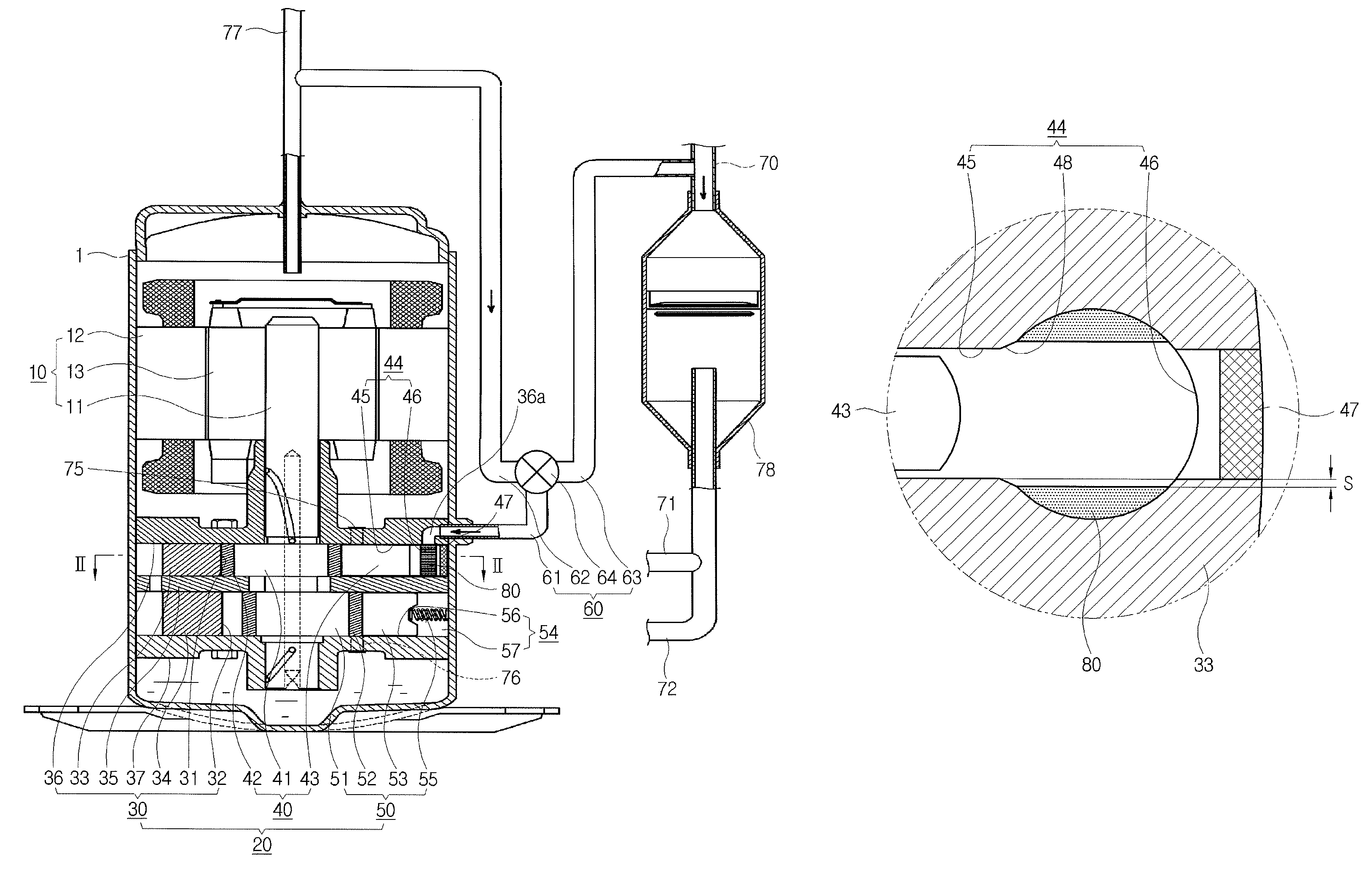
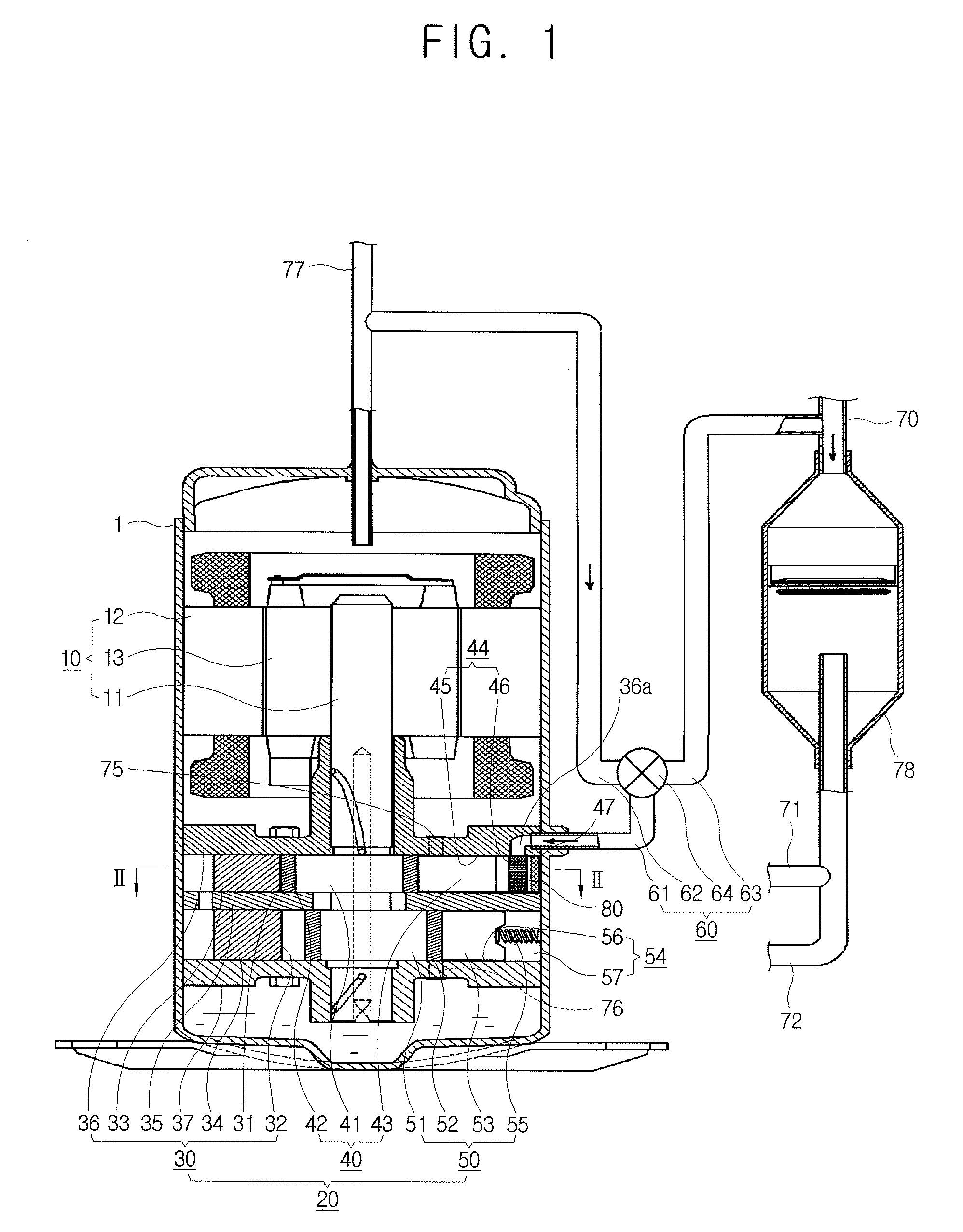
[0033]As illustrated in FIG. 1, a rotary compressor according to an embodiment of the present general inventive concept includes a gearing part 10 installed in an upper inner part of an airtight container 1, and a compressing part 20 installed in a lower inner part of the airtight container 1 and connected with the gearing part 10 by a rotating shaft 11.

[0034]The gearing part 10 includes a stator 12 fixed to an inner surface of the airtight container 1 and having a cylindrical shape, and a rotor 13 rotatably disposed inside the stator 12 and coupled to the rotating shaft 11 by a central part thereof. When power is supplied, the rotor 1...


PUM


Abstract

A rotary compressor including a cylinder to form a compression chamber, and including a vane slot including a vane guide part recessed outward from an inner surface of the compression chamber and an extended part having a width wider than the width of the vane guide part by a predetermined extension width in an outer end area of the vane guide part, a roller to eccentrically rotate in the compression chamber and to compress a medium, a vane reciprocatingly accommodated in the vane slot, and contacted to an outer surface of the roller to divide the compression chamber, and a filling member accommodated in a space of the extension width in the extended part.

Description

CROSS-REFERENCE TO RELATED APPLICATIONS[0001]This application claims priority under 35 U.S.C. § 119(a) from Korean Patent Application No. 2006-0083056, filed Aug. 30, 2006, in the Korean Intellectual Property Office, the disclosure of which is incorporated herein in its entirety by reference.BACKGROUND OF THE INVENTION[0002]1. Field of the Invention[0003]The present general inventive concept relates to a rotary compressor, and more particularly, to a rotary compressor with a variable capacity.[0004]2. Description of the Related Art[0005]A conventional cooling apparatus applied to an air conditioner or a refrigerator employs a variable capacity rotary compressor having a variable cooling ability for optimum cooling, and a variable coolant compressing ability for energy saving.[0006]As disclosed in Korean Patent First Publication No. 2004-21140, the variable capacity rotary compressor includes a housing formed with a compression chamber, a rotating shaft having an eccentric part rotat...

Claims


Application Information

Patent Timeline
Patent Type & Authority Patents(United States)
IPC IPC(8): F04C18/356F04C23/00
CPCF01C21/0809F01C21/0836F04C18/3564F04C23/001F04C23/008F04C28/065F04C29/02
Inventor LEE, MOON-JOOLEE, JEONG-BAEHAN, KYUNG-JUNSUNG, CHUN-MOSHIN, CHANG-JOO
Owner SAMSUNG ELECTRONICS CO LTD
Features
  • R&D
  • Intellectual Property
  • Life Sciences
  • Materials
  • Tech Scout
  • Unparalleled Data Quality
  • Higher Quality Content
  • 60% Fewer Hallucinations
Learn More