
Micropump, micropump unit including the micropump, sample processing chip for use with the unit, and sheet connector for use with the unit

Inactive Publication Date: 2010-02-09
PANASONIC CORP
View PDF6 Cites 4 Cited by
  • Summary
  • Abstract
  • Description
  • Claims
  • Application Information

AI Technical Summary

Benefits of technology

[0020]The present invention aims at providing a micropump which can be formed in a chip module in a microstructure; which has superior ease of transport, a superior sealing characteristic, and superior responsiveness; and which enables sliming, recycling, and easy assembly.
[0024]By means of this configuration, the present invention can facilitate assembly of a micropump which can be formed on a chip with a microstructure; which has a superior ease of transport, a superior sealing characteristic, and superior responsiveness; and which can be made slim and recycled.
[0026]By means of such a configuration, a micropump can be formed in a micro-chip-module. The reaction agent is controlled by a reaction start section, and hence a predetermined characteristic can be stably achieved by means of easy control. Since the recognition means determines whether or not a match exists between another chip and the structure pump material in terms of a position and a combination, erroneous placement of another chip or occurrence of a faulty operation are prevented, and hence the micropump is safe and economical.
[0029]By means of such a configuration, the detection means detects the pressure or flow rate of the gas and performs feedback control such that the pressure or flow rate approaches a predetermined target level. Hence, control can be carried out such that the pressure and flow rate have predetermined stable characteristics. The reaction start section and the reaction agent are stacked into a microstructure, and hence reaction for generating a gas can be performed at high speed. Since the micropump has superior responsiveness and great transport power and can be slimmed, assembly of the micropump by stacking the micropump on another chip is easy. The reaction start section is stacked as a separate member, and hence the micropump can be recycled.
[0030]A micropump unit of the invention has a pump structure material having a plurality of independent micropumps formed therein and enables the respective micropumps to be employed solely or in combination. Since the micropumps are provided independently, a plurality of samples are supplied through use of one chip so as to react with each other, and the result of reaction can be detected. The respective micropumps have microstructures and can be assembled into a chip module, thereby achieving superior responsiveness, a reduction in thickness, recycling, and easy assembly.
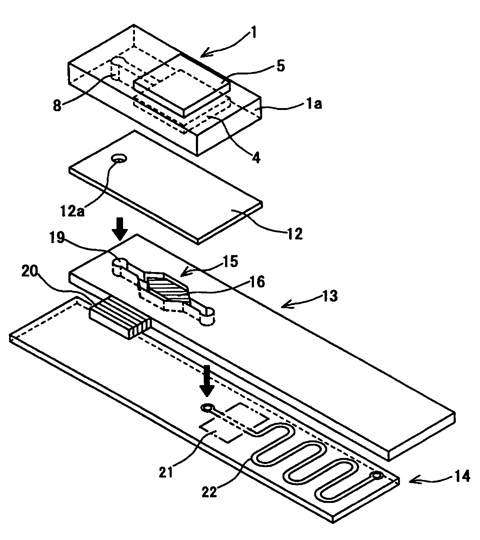
[0031]A sample processing chip of the invention has the micropump; a flow passage control chip which is stacked on the micropump, and supplies a sample by means of the gas ejected from the micropump, thereby controlling a flow passage; and a processing chip for processing the sample supplied from the flow passage control chip. The micropump, the flow passage control chip, and the processing chip are stacked one on top of the other and can be made compact, slim, and easy to process.

Problems solved by technology

If control of the micropump is neither easy nor accurate, the pump cannot be used as an element for the hydraulic circuit.
Hence, there are achieved only a small pumping characteristic, a low delivery pressure, and low discharge capacity.
If liquid to be ejected is changed while such a pump having a fine and complicated structure is used, the entire micropump must be discarded, because cleansing of the inside of the pump is not easy, and would incur high running costs.
An attempt to increase the stroke of the diaphragm through use of a piezoelectric element also encounters a limitation.
However, the conventional electrochemical-cell-drive pump basically fails to have a structure suitable for mounting the pump on a chip.
Hence, adoption of this electrochemical-cell-drive pump as a micropump is difficult.

Method used


Image

  • Micropump, micropump unit including the micropump, sample processing chip for use with the unit, and sheet connector for use with the unit
  • Micropump, micropump unit including the micropump, sample processing chip for use with the unit, and sheet connector for use with the unit
  • Micropump, micropump unit including the micropump, sample processing chip for use with the unit, and sheet connector for use with the unit

Examples


first embodiment

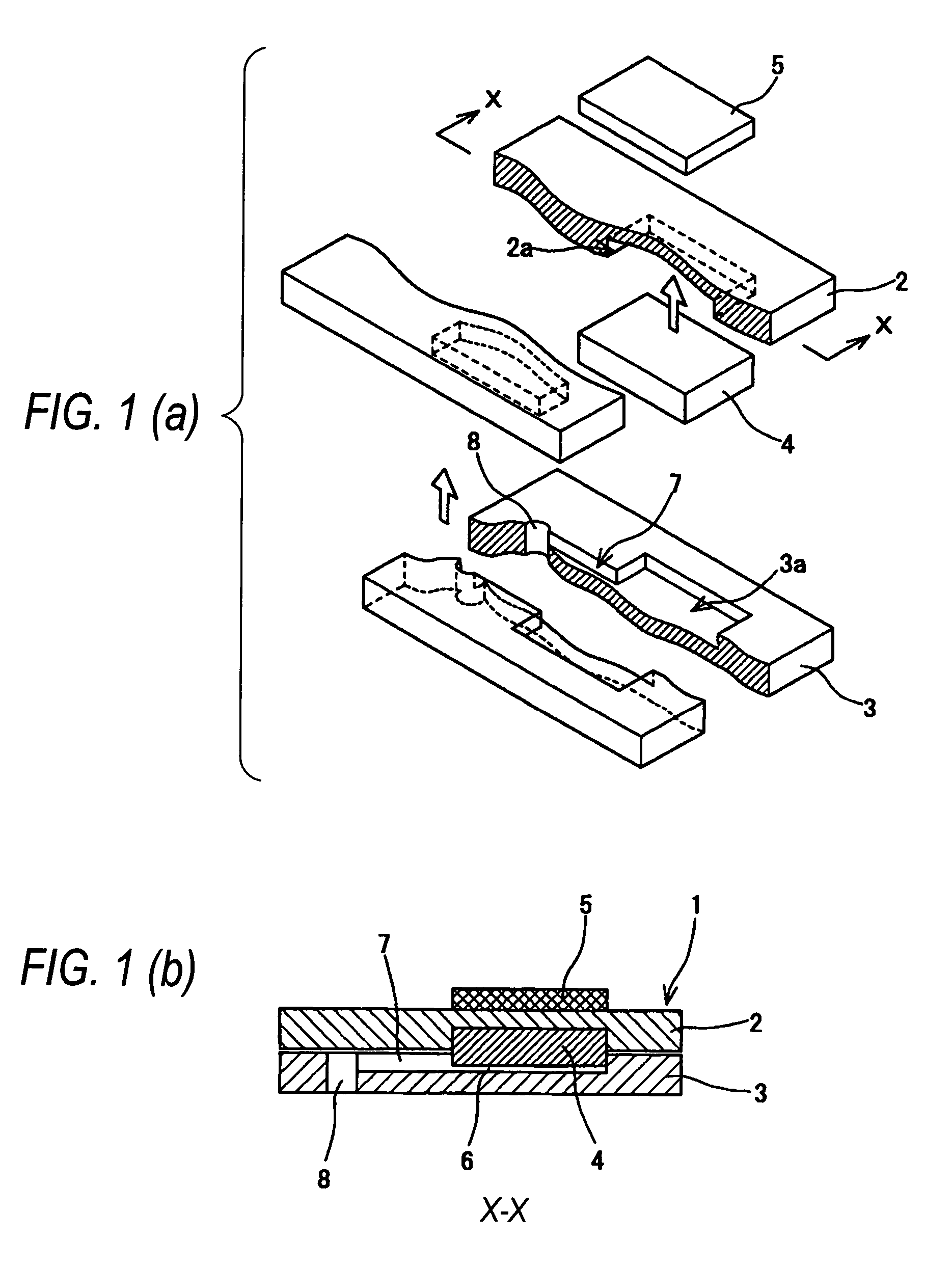
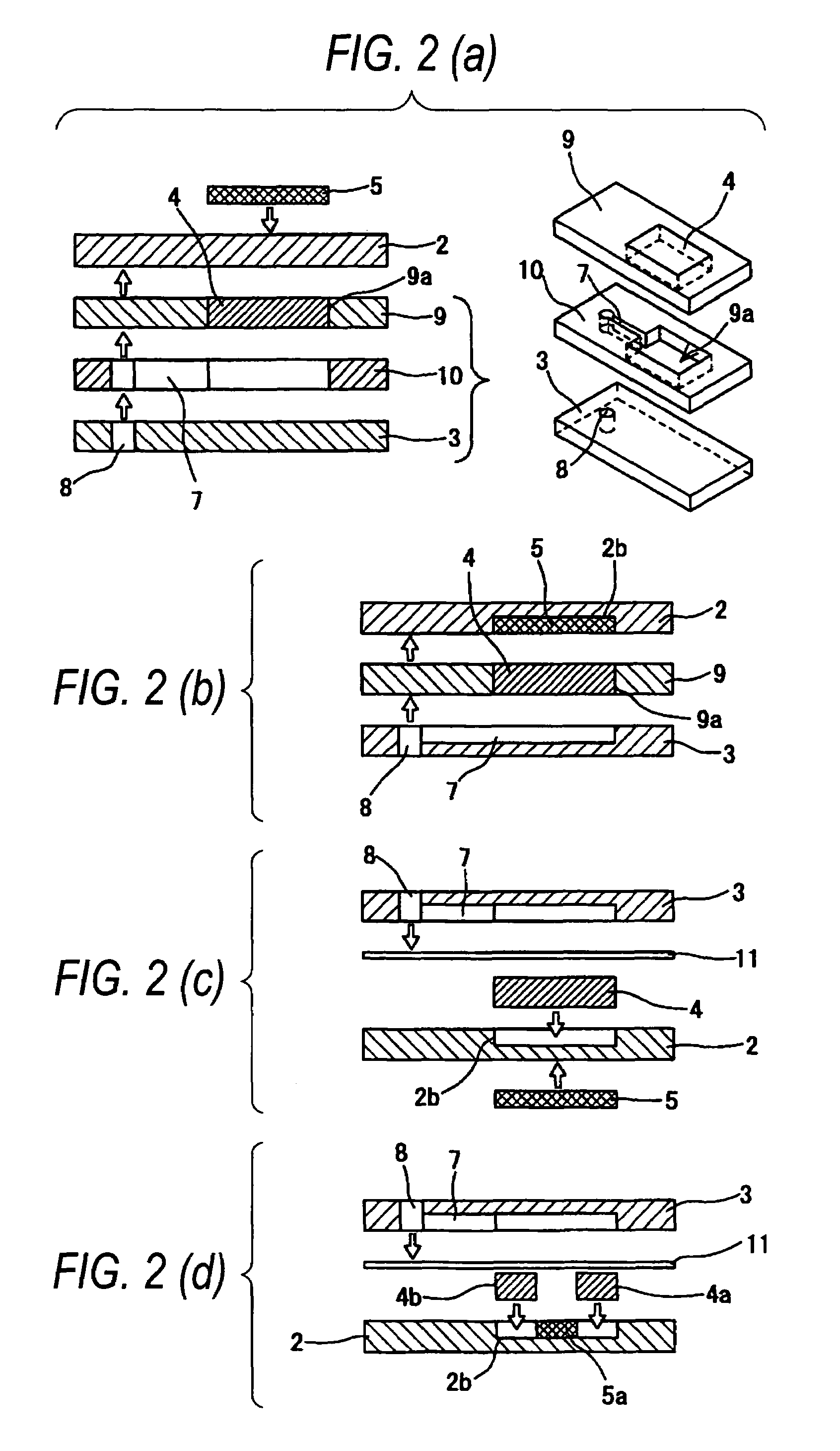
[0093]FIG. 1A is an exploded descriptive view of a micropump according to a first embodiment of the invention; FIG. 1B is a cross-sectional view of the micropump shown in FIG. 1A taken along line X-X; and FIGS. 2A to 2D are exploded descriptive views of another configuration of the micropump according to the first embodiment of the invention.

[0094]In FIGS. 1A and 1B, reference numeral 1 designates a micropump which produces a high-pressure gas by means of chemical reaction, to thereby transfer, by means of the high pressure gas, a sample M stored in a reservoir of another chip remaining in communication with the micropump; 2 designates a first structural material of the micropump 1; 2a designates an indentation formed in the first structural material 2 (i.e., a first indentation of the invention); 3 designates a second structural material of the micropump 1; and 3a designates an indentation formed in the second structural material 3 (a second indentation of the invention). Reference...

second embodiment

[0103]There will now be described another micropump which is suitable for use in combination with another chip module, such as a flow passage control chip and a reaction detection chip. FIG. 3A is an exploded perspective view of a sample processing chip in which micropumps according to a second embodiment of the invention are stacked; FIG. 3B is a fragmentary broken enlarged view of a flow passage control chip constituting the sample processing chip shown in FIG. 3A; FIG. 4A is an exploded cross-sectional view of the sample processing chip in which the micropumps of the second embodiment of the invention are stacked; and FIG. 4B is an exploded cross-sectional view of a sample processing chip in which the micropumps of the second embodiment of the invention and a reaction detection section are combined together. In FIGS. 3A and 3B, reference numeral 1a designates a pump chip (i.e., a pump structural material of the invention) constituting a micropump main body exclusive of the reacti...

third embodiment

[0112]The micropumps that have been described above each comprise the reaction initiation means serving as a drive source and the reaction agent, and pressurize a sample with a produced gas. However, there will now be described a micropump according to a third embodiment employing a special drive source. FIG. 5A is an exploded cross-sectional view of a sample processing chip on which micropumps according to a third embodiment of the invention are stacked; and FIG. 5B is an exploded cross-sectional view of the sample processing chip into which the micropumps of the third embodiment of the invention and circuit boards are combined together.

[0113]A micropump shown in FIG. 5A is of suction type. Reference numeral 1c designates a suction micropump which aspirates a gas. Reference numeral 4C designates a gas absorbing material; 5b designates absorption initiation means for commencing absorption of a gas; 7a designates a channel which performs sucking of the sample M from the reservoir 19 ...


PUM


Abstract

The present invention relates to a device which is to be utilized at the time of observation of a mixed state or a chemically-combined state of a mixture attained by mixing together trace amounts of gases or trace amounts of liquids or mixing a trace amount of a gas with a trace amount of liquid. A micropump 1 comprises a pump structural material having a reaction chamber formed therein; a reaction agent 4 which is housed in a reaction chamber 6 and produces a gas of predetermined pressure; reaction initiation means 5 which is disposed beside the reaction agent and causes the reaction agent to produce a gas; and a channel 7 which is provided in the pump structural material and guides the gas of predetermined pressure produced by the reaction agent from the reaction chamber to an outlet port. The pump structural material and the reaction initiation means are stacked one on top of the other.

Description

CROSS REFERENCE TO RELATED APPLICATION[0001]This application is based upon and claims the benefit of priority of Japanese Patent Application No P2002-366567 filed on Dec. 18, 2002 and Japanese Patent Application No P2003-000949 filed on Jan. 7, 2003, and Japanese Patent Application No P2003-002051 filed on Jan. 8, 2003 the contents of which are incorporated herein by reference in its entirety.BACKGROUND OF THE INVENTION[0002]1. Field of the Invention[0003]The present invention relates to a device utilized at the time of mixing together trace amounts of gases, trace amounts of liquids, or trace amounts of gas and liquid and observing a mixed state or a combined state of the resultant mixture.[0004]2. Description of the Related Art[0005]Recent progress in nanotechnology and ultramicro processing techniques is remarkable, and combination of these technologies is henceforth expected to evolve into various applications.[0006]A technology pertaining to a micro-electromechanical system (ME...

Claims


Application Information

Patent Timeline
IPC IPC(8): G01N33/00B01J19/00B01L3/00F04B19/24F04B43/04
CPCB01J19/00B01J19/0093B01L3/50273F04B19/24F04B43/043B01J2219/00783B01J2219/00844B01J2219/00891B01J2219/0095B01L2200/025B01L2200/146B01L2300/044B01L2300/0816B01L2300/0887B01L2400/046
Inventor TAKEDA, MASATOSHINAKANO, KENICHI
Owner PANASONIC CORP
Learn More