

Method for manufacturing float valve apparatus
a technology of float valves and valve seats, applied in non-electric welding apparatus, welding/cutting auxillary devices, auxillary welding devices, etc., can solve the problems of valve seat ring lateral slippage, hole deformation of valve seat ring, and reduce the circularity of the valve seat ring, so as to prevent the inclination of the seal cap
- Summary
- Abstract
- Description
- Claims
- Application Information
AI Technical Summary
Benefits of technology
Problems solved by technology
Method used
Image

Examples
Embodiment Construction
[0025]An embodiment of the invention will be described below based on the drawings.
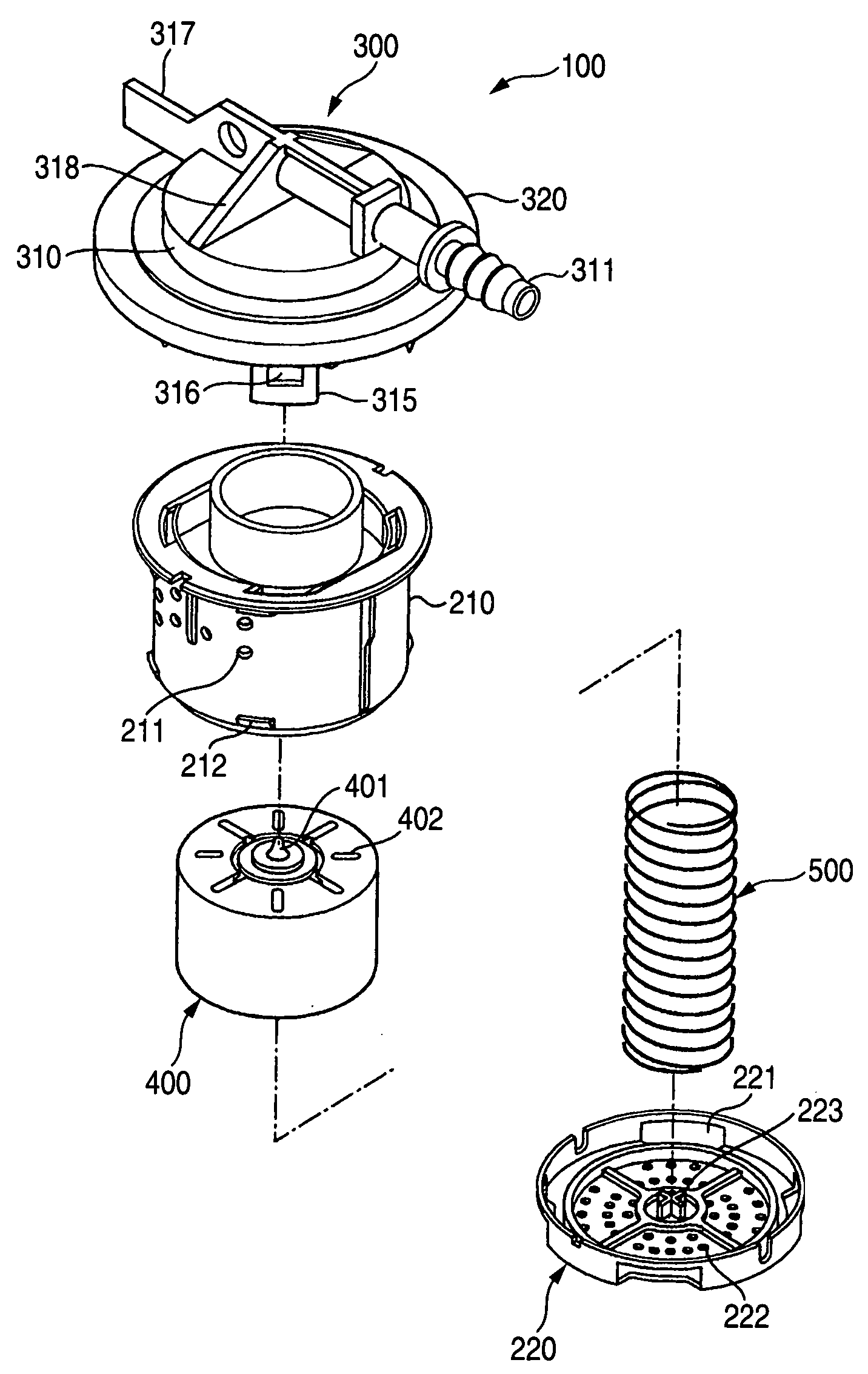
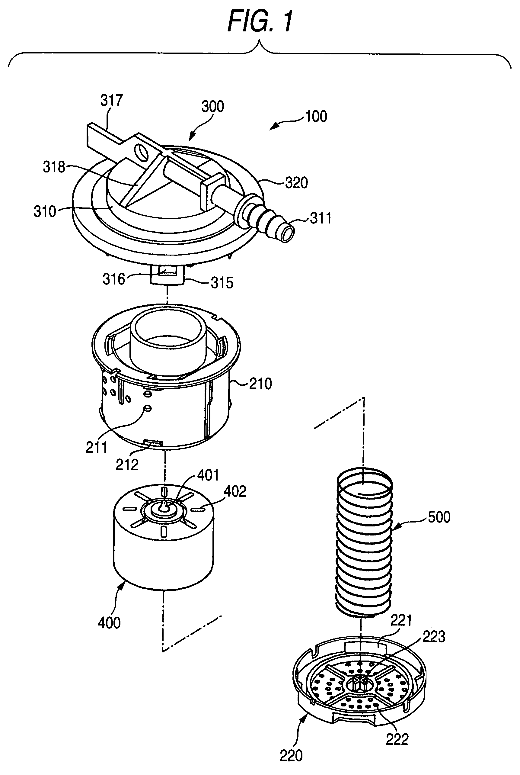
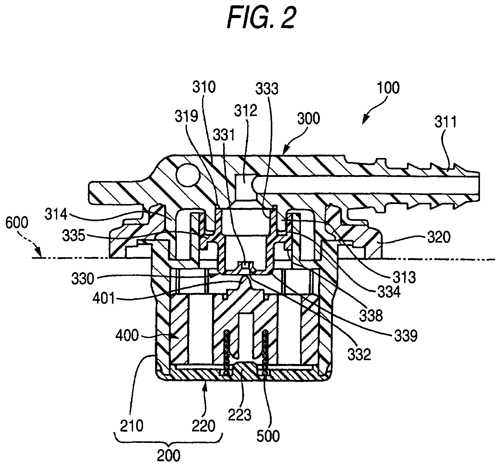
[0026]One embodiment of a float valve apparatus manufactured by the invention is shown in FIGS. 1 to 7. FIG. 1 is an exploded perspective view of a float valve apparatus, and FIG. 2 is a sectional view showing a state in which the float valve apparatus is mounted in a fuel tank, and FIGS. 3A and 3B are enlarged sectional views of a weld part in the case of spin welding a seal cap to a lid body and FIG. 3A is an enlarged sectional view before welding and FIG. 3B is an enlarged sectional view after welding, and FIG. 4 is a sectional view showing a state before spin welding in the case of spin welding the seal cap to the lid body, and FIG. 5 is a sectional view showing a state after spin welding in the case of spin welding the seal cap to the lid body, and FIG. 6 is a perspective view showing a welding method of the seal cap by a spin welding apparatus, and FIG. 7 is a perspective view showing a rotary h...
PUM
| Property | Measurement | Unit |
|---|---|---|
| diameter | aaaaa | aaaaa |
| vibration energy | aaaaa | aaaaa |
| angle | aaaaa | aaaaa |
Abstract
Description
Claims
Application Information