Ambidextrous bolt catch for firearms

a bolt catch and accessory technology, applied in the field of firearms, can solve the problems of difficult and sometimes impossible to actuate with a single hand while aiming the firearm, save valuable time in the field, and reduce inventory. cost, the effect of saving valuable tim

Active Publication Date: 2010-02-16
KNIGHT'S ARMAMENT COMPANY
View PDF24 Cites 124 Cited by
  • Summary
  • Abstract
  • Description
  • Claims
  • Application Information

AI Technical Summary

Benefits of technology

[0043]The plunger rod assembly can include a torsion spring surrounding the first end of the plunger rod, held in place by a plunger head, the torsion spring creates tension and causes rotation of the bolt catch finger in a downward position when the first release lever and second release lever are pressed laterally toward the right side and the left side of the weapon and when the first release lever and second release lever are pulled laterally away from the right side and the left side of the rifle, the bolt catch finger rotates to an upward position.

Problems solved by technology

On most firearms the bolt catch is located on one side of the receiver, making it difficult and sometimes impossible to actuate with a single hand while aiming the firearm.
Such an improvement saves valuable time in the field and significant costs in inventory.

Method used


Image

  • Ambidextrous bolt catch for firearms
  • Ambidextrous bolt catch for firearms
  • Ambidextrous bolt catch for firearms

Examples


Embodiment Construction

[0054]Before explaining the disclosed embodiment of the present invention in detail, it is to be understood that the invention is not limited in its application to the details of the particular arrangement shown since the invention is capable of other embodiments. Also, the terminology used herein is for the purpose of description and not of limitation.

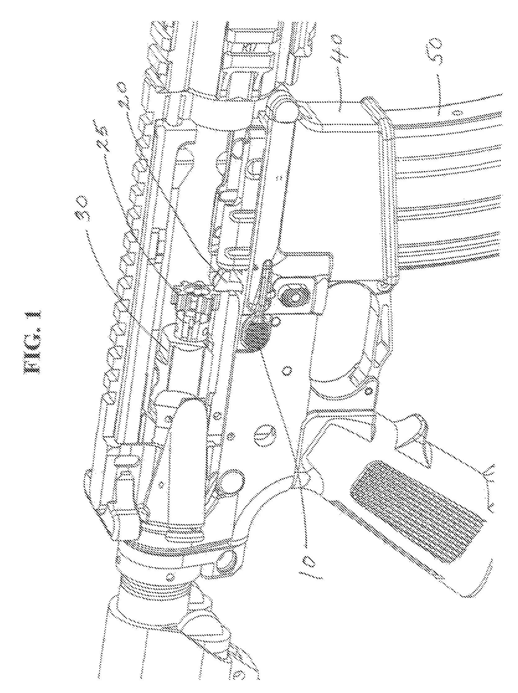
[0055]It would be useful to discuss the meanings of some words used herein and their applications. “Firearm” is used herein to refer to all weapons to which an ambidextrous bolt catch device can be installed, such as those having or capable of being manufactured with mounting holes in the receiver. A preferred weapon for installing the present invention is the M16 / M4 family of weapons.

[0056]The directional terms “lateral,”“horizontal,”“vertical,”“front,”“forward,”“rear,”“rearward,”“right,”“left,”“above,” and “below” refer to the firearm when held in the normal firing position.

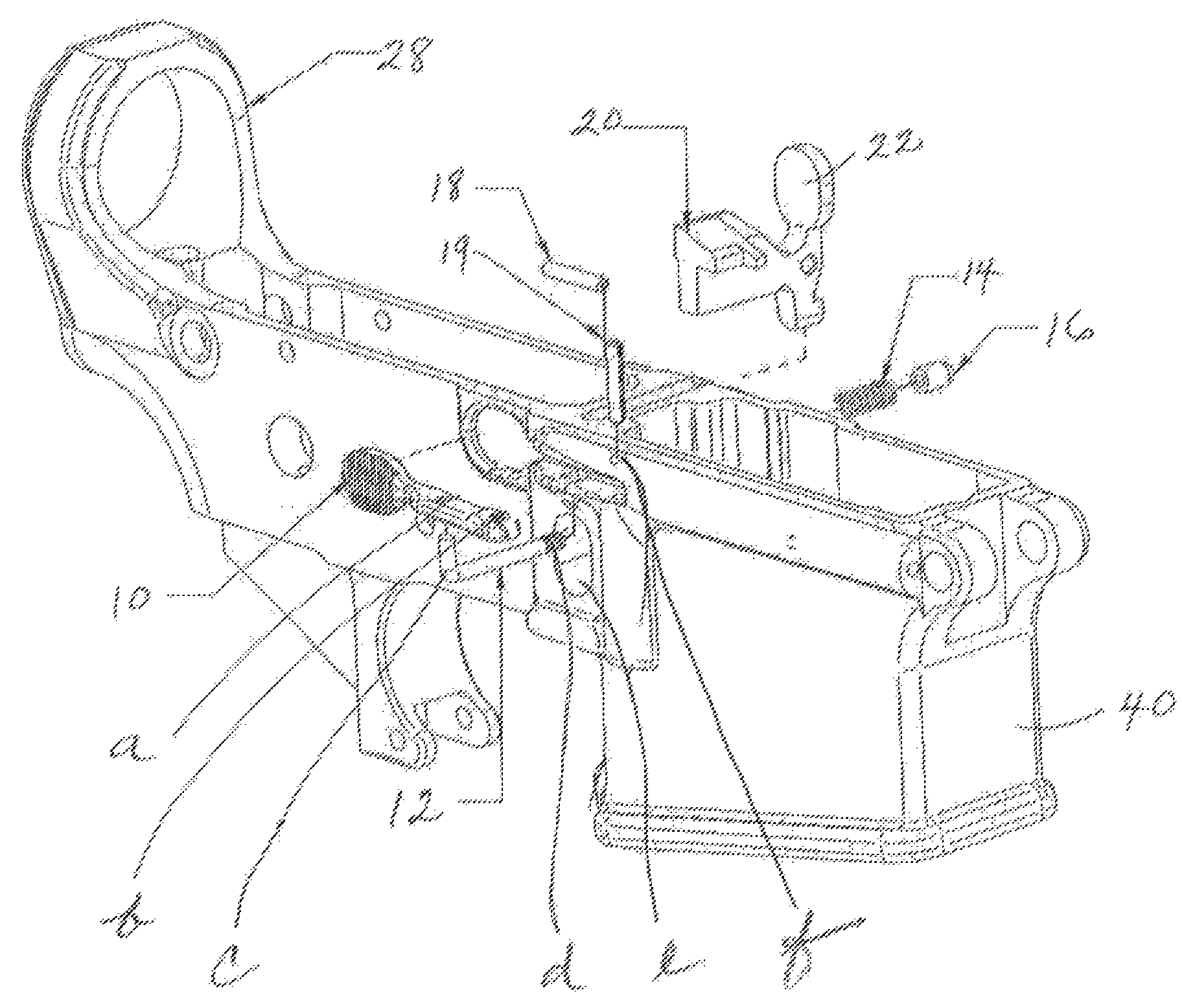
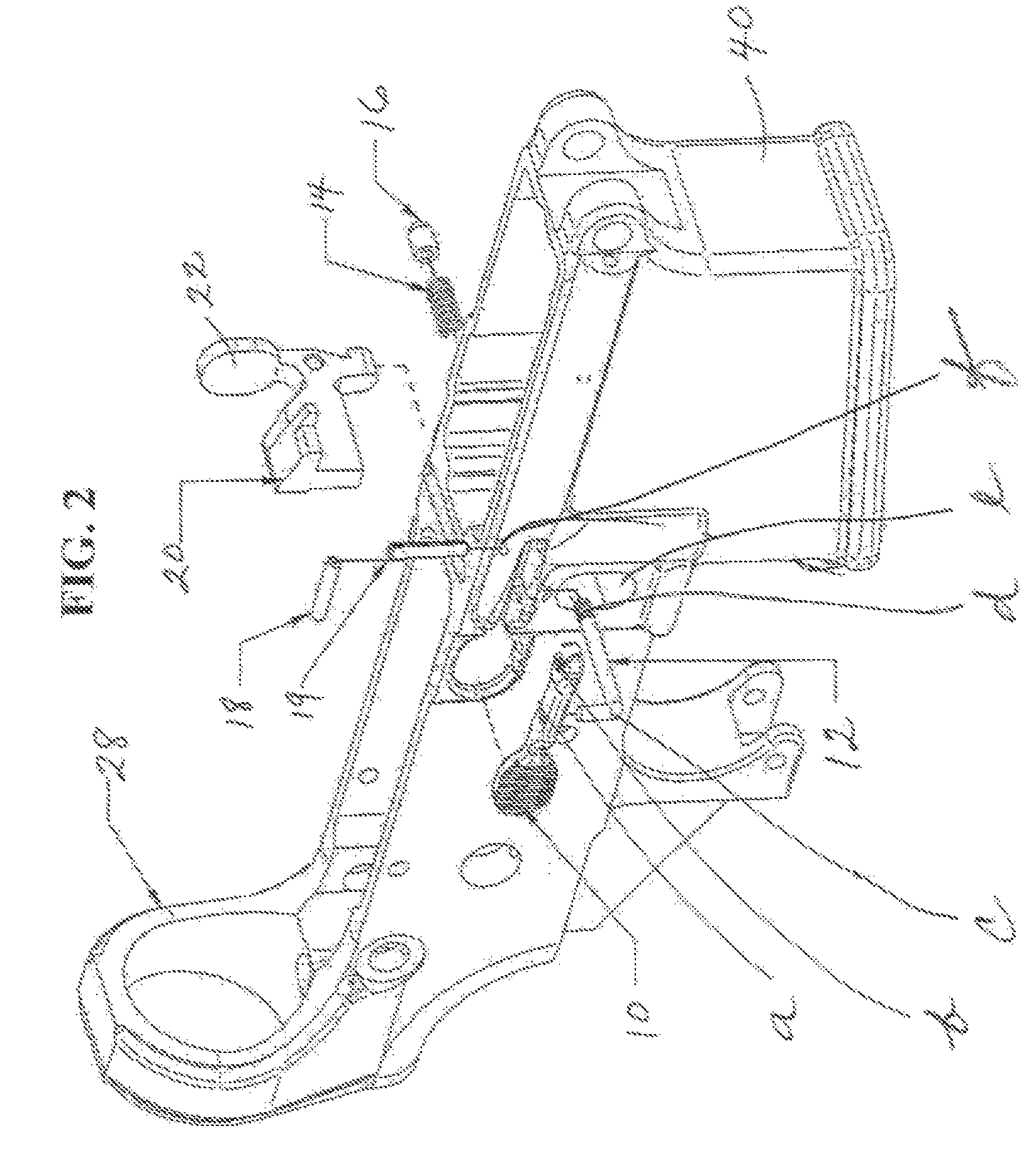
[0057]Listed below are the components of the ambidextrous b...


PUM


Abstract

An ambidextrous bolt catch device, apparatus, system and methods for using are provided. Four main components include a bolt catch finger, lever system and plunger rod assembly with torsion spring. The lever system includes a right release lever and a left release lever; the left lever is an integral part of the bolt catch finger. The plunger rod assembly abuts and connects the right and left levers; a torsion spring on the rod creates tension causing rotation of the bolt catch finger in a downward or upward position. In an upward position, the bolt catch finger engages the bolt, retains the bolt in a rearward position, and signals the operator that the magazine is empty. The bolt engaged by the finger is held rearward in a safe, reliable manner to allow an unobstructed view of the firearm chamber until manually released using either the right or left release lever.

Description

[0001]This invention claims the benefit of priority of U.S. Provisional Patent Application Ser. No. 60 / 879,639 filed Jan. 10, 2007.FIELD OF THE INVENTION[0002]The present invention relates to a firearm, and particularly, to an ambidextrous bolt catch device, apparatus, system and method on a semi-automatic or fully automatic firearm that retains the bolt and bolt carrier mechanism in a rearward position.BACKGROUND AND PRIOR ART[0003]Bolt catch devices for hand-held firearms are known in the art, especially in handguns and combat rifles. The purpose of a bolt catch device on any firearm is to retain the principal members of the bolt or bolt carrier mechanism in a rearward position. The rear-hold position is desirable as a safety measure to allow an unobstructed view of the chamber of a firearm; to provide access to the chamber area for cleaning or clearing an obstruction, or other maintenance; as a signal to the operator that the magazine is empty; and to provide a means for rapid re...

Claims


Application Information

Patent Timeline
Patent Type & Authority Patents(United States)
IPC IPC(8): F41A17/34F41A3/42
CPCF41A3/42F41A35/06
Inventor KNIGHT, JR., C. REEDCALLAGHAN, MATTHEW A
Owner KNIGHT'S ARMAMENT COMPANY
Why Eureka
Try Eureka