Vibration damper having a buffer spring

a technology of vibration damper and buffer spring, which is applied in the direction of vibration damper, mechanical equipment, resilient suspension, etc., can solve the problems of pin stability, pin deformation or even separation, and the negative influence of the damping characteristic of the damping piston, etc., and achieve the effect of cost-effectiveness

Active Publication Date: 2010-02-16
THYSSENKRUPP BILSTEIN
View PDF10 Cites 6 Cited by
  • Summary
  • Abstract
  • Description
  • Claims
  • Application Information

AI Technical Summary

Benefits of technology

[0006]By virtue of the fact that a non-positive and / or positive locking connection is provided between the spring collar and the piston rod, a force exerted by the buffer spring onto the spring collar is introduced directly into the piston rod without the force being introduced onto the piston rod-side spring washers of the working piston and thus into the working piston itself. In this manner, forces emanating from the buffer spring do not have a disruptive influence on the damping characteristic of the working piston. Furthermore, high buffer forces are prevented from being introduced into the piston rod extension via the working piston. In this manner, possible deformations, damage or a possible separation of the piston rod extension are obviated.
[0009]Alternatively, the spring collar screwed onto the piston rod can lie with its end surface, remote from the piston, against a radial [lacuna] of the piston rod and can be supported on this shoulder. In this embodiment, the entire spring collar can have a smaller extension in the radial direction, i.e., it can have smaller diameters. As a result, the annular support surface, against which the buffer spring is supported, has a smaller diameter so that a closely wound buffer spring can be used which reduces the installation space and the weight.
[0011]If the shoulder of the end of the piston rod and the corresponding stop surface of the spring collar lying against this shoulder extend in the radial direction, then this contributes to a further reduction / minimisation of the axial installation height.
[0013]In order to ensure that the spring collar lies with its stop surface against the shoulder on the end of the piston rod, the second bore section of the stepped bore is provided at its end facing the first bore section with a recess. In this manner, the recess ensures that radial space is available in which the end of the piston rod is received without the end of the piston rod in the radial direction coming into contact with the material of the spring collar. As a result, the stop surface of the spring collar can lie completely against the shoulder on the end of the piston rod.
[0015]A cost-effective buffer spring is formed as a helical spring formed of wound steel wire. It is particularly advantageous if the thread of the spring collar, by means of which the spring collar is screwed to the piston rod, has a pitch oriented in the opposite direction to the winding direction of the buffer spring. If the buffer spring formed as a helical spring is a spring having a right winding, then the spring collar has a left thread and vice-versa. This is advantageous in that torsional moments exerted by the buffer spring onto the spring collar do not cause the spring collar to become unscrewed but rather act in the direction in which the spring collar is fixedly screwed to the piston rod. In this manner, the screw connection between the spring collar and the piston rod cannot be undesirably loosened.

Problems solved by technology

A disadvantage in the known vibration damper resides in the fact that forces exerted by the buffer spring onto the disc body (the spring collar) are introduced directly into the working piston via the piston rod-side spring washers.
As a result, the damping characteristic of the damping piston is negatively influenced.
Furthermore, the forces exerted by the buffer spring onto the disc body (the spring collar) flow into the pin of the piston rod via the working piston which can lead to problems in terms of stability in the region of the pin.
In extreme cases, deformation or even separation of the pin can occur in the case of high buffer forces.

Method used


Image

  • Vibration damper having a buffer spring
  • Vibration damper having a buffer spring
  • Vibration damper having a buffer spring

Examples


Embodiment Construction

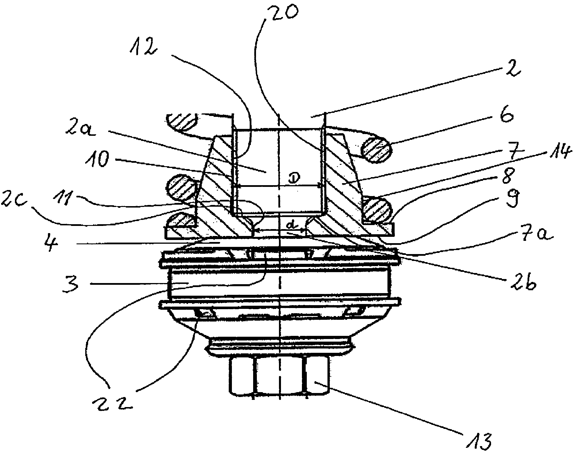
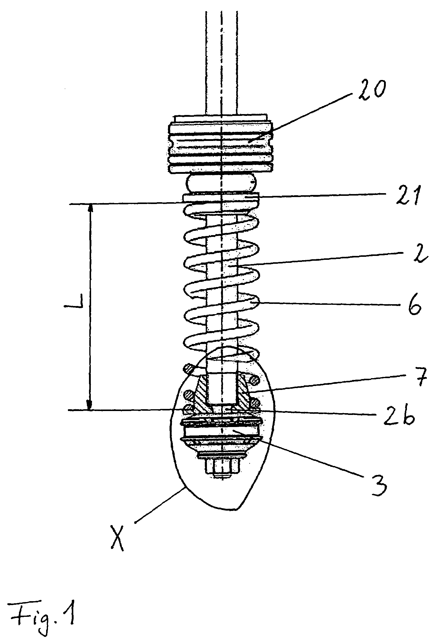
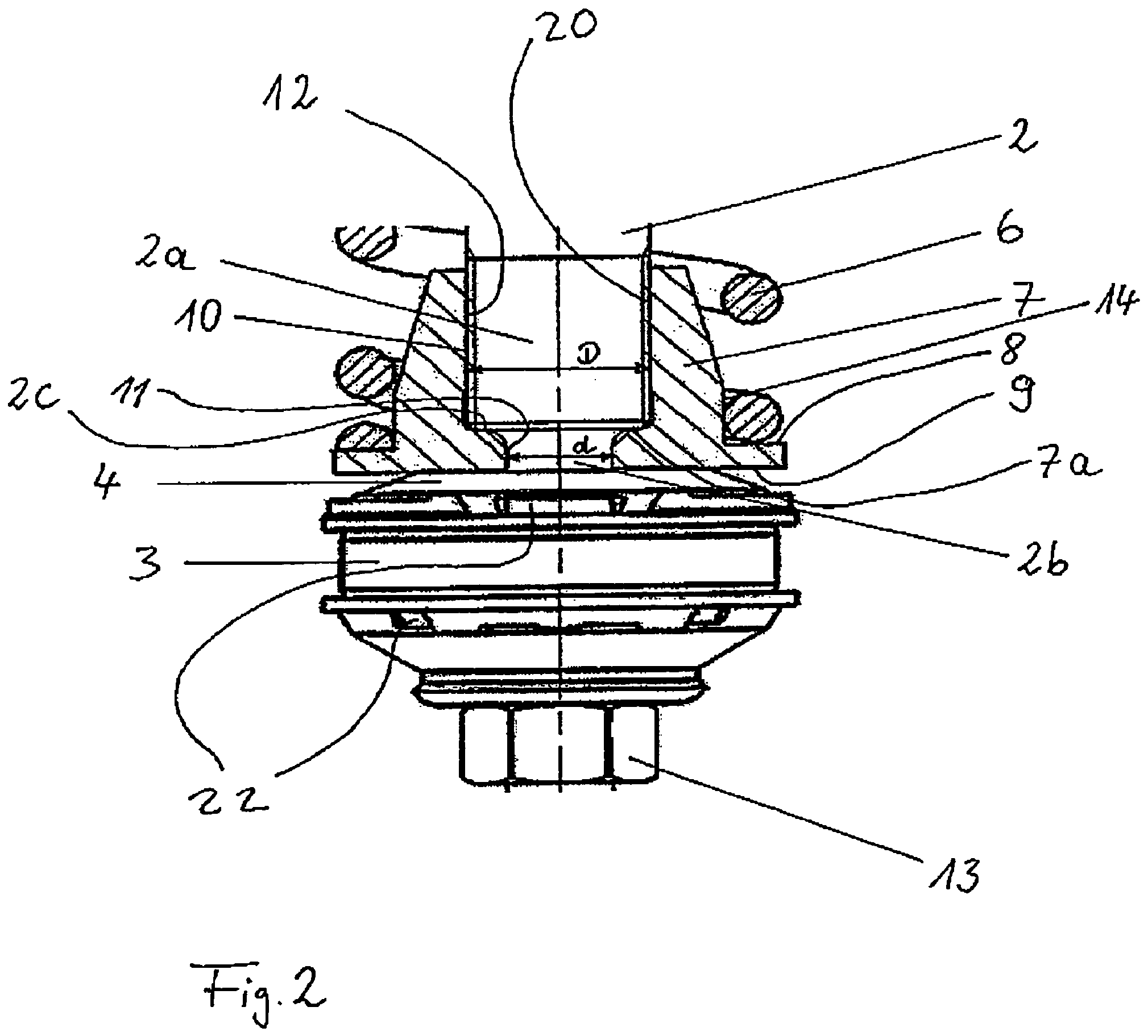
[0021]FIG. 1 illustrates an arrangement comprising a piston rod 2 having a piston rod extension 2b, a piston 3, a spring collar 7, a buffer spring 6 and a sealing and guiding unit 20, wherein the damper tube has been left out in order to illustrate the invention more clearly. A support plate 21 is provided on the side of the sealing and guiding unit 20 facing the working piston and the buffer spring 6 is supported against the support plate with its end remote from the working piston.

[0022]The axial installation length between the support plate 21 and the first support surface 8 of the spring collar 7 is designated with L in FIG. 1. The point of the invention is to make this axial installation length L as large as possible and simultaneously to ensure that forces and moments exerted by the buffer spring 6 onto the spring collar 7 are introduced directly into the piston rod 2. Owing to the large axial installation space for the buffer spring 6, its length can be maximised in the case ...


PUM


Abstract

A vibration damper is disclosed which includes a damper tube filled with a damping medium; a piston rod which can move in an oscillating and reciprocal manner in the damper tube and one end of which protrudes into the damper tube and which comprises at this end a piston rod extension and a shoulder. A piston divides the interior of the damper tube into a working chamber remote from the piston rod and a piston rod-side working chamber and which is disposed coaxially with respect to the piston rod extension and comprises restrictor openings and at least one spring washer covering these restrictor openings in each working chamber. A buffer spring is disposed in the piston rod-sideworking chamber.

Description

BACKGROUND OF THE INVENTION[0001]The invention relates to a vibration damper having: a damper tube filled with a damping medium; a piston rod which can move in an oscillating and reciprocal manner in the damper tube and one end of which protrudes into the damper tube and which comprises at this end a piston rod extension and a shoulder; a piston which divides the interior of the damper tube into a working chamber remote from the piston rod and a piston rod-side working chamber and which is disposed coaxially with respect to the piston rod extension and comprises restrictor openings and at least one spring washer covering these restrictor openings in each working chamber; a buffer spring disposed in the piston rod-side working chamber; and also a spring collar which is disposed in the piston rod-side working chamber and has a first support surface supporting the buffer spring and a second support surface for the at least one spring washer disposed in the piston rod-side working chamb...

Claims


Application Information

Patent Timeline
Patent Type & Authority Patents(United States)
IPC IPC(8): F16F9/00
CPCF16F9/585
Inventor FRITZ, MICHAELKLEIN, UWE
Owner THYSSENKRUPP BILSTEIN
Why Eureka
Try Eureka