Ball bearing assembly for bicycle

a technology for bicycles and bearings, applied in the direction of bearing units, cycle equipments, steering devices, etc., can solve the problems of poor structural stability, material or structural properties of conventional packing rings b>25/b> might incur problems, and conventional packing rings are subject to deformation, etc., to achieve high tensile strength, high fracture strength, and good rigidity

Inactive Publication Date: 2010-02-16
COMPONENTS
View PDF5 Cites 3 Cited by
  • Summary
  • Abstract
  • Description
  • Claims
  • Application Information

AI Technical Summary

Benefits of technology

[0008]The present invention has been accomplished under these circumstances in view. It is one objective of the present invention to provide an improved ball bearing assembly to prevent problems occurred in prior arts.
[0016]The efficacy of the present invention is that the disclose ball bearing assembly possesses structural stability, assembling accuracy, and automatic center adjusting function. Regarding assembling accuracy, as the packing ring is made by means of plastic injection molding, it is characterized by being stable, well rigid, high tensile strength, high fracture strength, flexible, and light-weighted. The axial length, cone-shaped outer surface and flange can be precisely formed integrally so that the resultant packing ring is facile for being assembled with the cap from the center hole and in turn the inner race can be axially positioned in the cap without miss by the presence of the flange. As assembling accuracy is ensured, structural stability assembly of the entire assembly can be consequently achieved. Additionally, the packing ring also facilitates center adjusting for holding components that are concentrically assembled therewith (e.g. the front fork stem settled in the head tube) at proper relative positions.

Problems solved by technology

However, some material or structural properties of conventional packing ring 25 might incur problems.
Thus it can be seen that the conventional packing ring are subject to deformation and poor structural stability.
With such a conventional packing ring, the fastening between the inner race and ball cage can be consequently affected and therefore the assembling accuracy of the entire ball bearing assembly can be in turn depressed.

Method used


Image

  • Ball bearing assembly for bicycle
  • Ball bearing assembly for bicycle
  • Ball bearing assembly for bicycle

Examples


Embodiment Construction

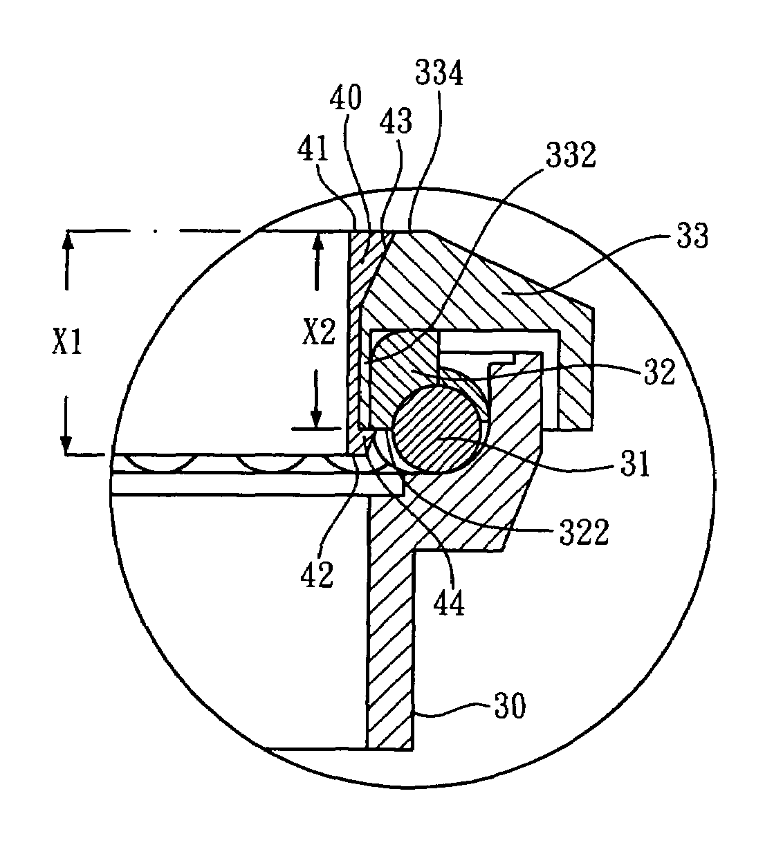
[0024]As can be seen in FIGS. 3, 4 and 5, the ball bearing assembly according to the present invention primarily comprises an outer race 30, a ball cage 31, an inner race 32, a cap 33 and a packing ring 40. The ball cage 31 is settled in the outer race 30, and the inner race 32 is positioned correspondingly to the inner top surface of the cap 33. Further, the cap 33 is hooded onto the outer race 30 so that the inner race 32 is pressed on to the ball cage 31 whereupon when the packing ring 40 is inserted form a center hole 331 of the cap 33, the inner race 32 can be radially secured within the cap 33.

[0025]Particularly, the cap 33 of the disclosed subject matter has its center hole 331 formed diametrically corresponding to the inner diameter of the inner race 32 and has the periphery of the center hole 331 extended cent ripe tally to form a ring portion 332 with an axial length equal to that of the inner race 32. Thereby, the inner race 32 can has its inner surface closely surroundin...


PUM


Abstract

A ball bearing assembly for a bicycle comprises a outer race, a ball cage, settled in the outer race, a cap, having a center hole and a ring portion extended axially from the periphery of the center hole, an inner race, with the inner surface thereof closely surrounding the outer surface of the ring portion, and a packing ring which is in an annular shape and having an annular flange around the bottom outer edge so that when the cap is put over the outer race to make the ball cage press upon the ball cage, the packing ring can be inserted into the center hole of the cap, and the flange is retained around the bottom of the ball cage. The disclosed ball bearing assembly is characterized by improved assembling accuracy and automatic center adjusting function.

Description

BACKGROUND OF THE INVENTION[0001]1. Technical Field[0002]The present invention relates to a ball bearing assembly for a bicycle, and more particularly, to a ball bearing assembly characterized by improved assembling accuracy and automatic center adjusting function.[0003]2. Description of Related Art[0004]The exposition of ball bearing assembly is herein started with a bicycle headset structure, as shown in FIGS. 1 and 2, implementing an upper ball bearing assembly 20 and a lower ball bearing assembly 10.[0005]As can be seen in the drawings, the lower ball bearing assembly 10 comprises an outer race 11, a ball cage 12 and an inner race 13. The inner race 13 is mounted onto a socket 92 positioned between a front fork stem 90 and a front fork 91 of the bicycle. Sequentially, the ball cage 12 is mounted onto the inner race 13 and the outer race 11 is combined with the bottom edge of a head tube 93 of the bicycle. As the front fork stem 90 is pierced into the head tube 93, the ball cage ...

Claims


Application Information

Patent Timeline
Patent Type & Authority Patents(United States)
IPC IPC(8): F16C13/00
CPCB62K21/06F16C35/073F16C19/54F16C2326/26
Inventor LIN, WEN-HWA
Owner COMPONENTS
Why Eureka
Try Eureka