Mounting apparatus for expansion card

Inactive Publication Date: 2010-02-16
HON HAI PRECISION IND CO LTD
View PDF5 Cites 20 Cited by
  • Summary
  • Abstract
  • Description
  • Claims
  • Application Information

AI Technical Summary

Problems solved by technology

However, the fixing plates may block airflow to the expansion card.
In a chassis having a plurality of expansion cards fixed in para

Method used


Image

  • Mounting apparatus for expansion card
  • Mounting apparatus for expansion card
  • Mounting apparatus for expansion card

Examples


Embodiment Construction

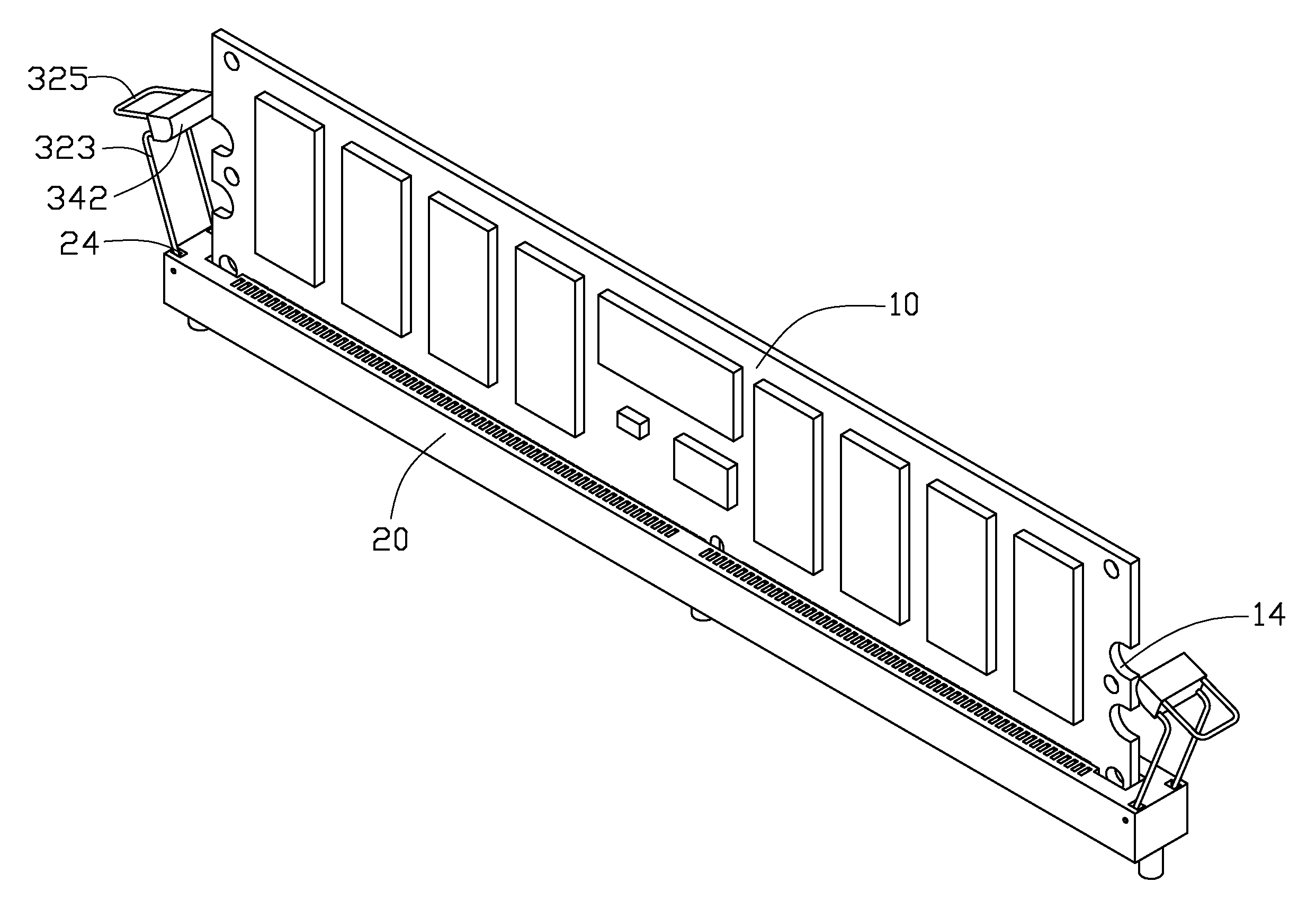
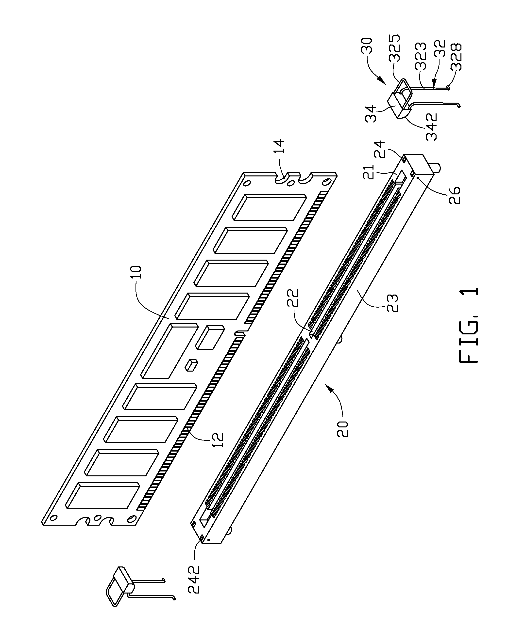
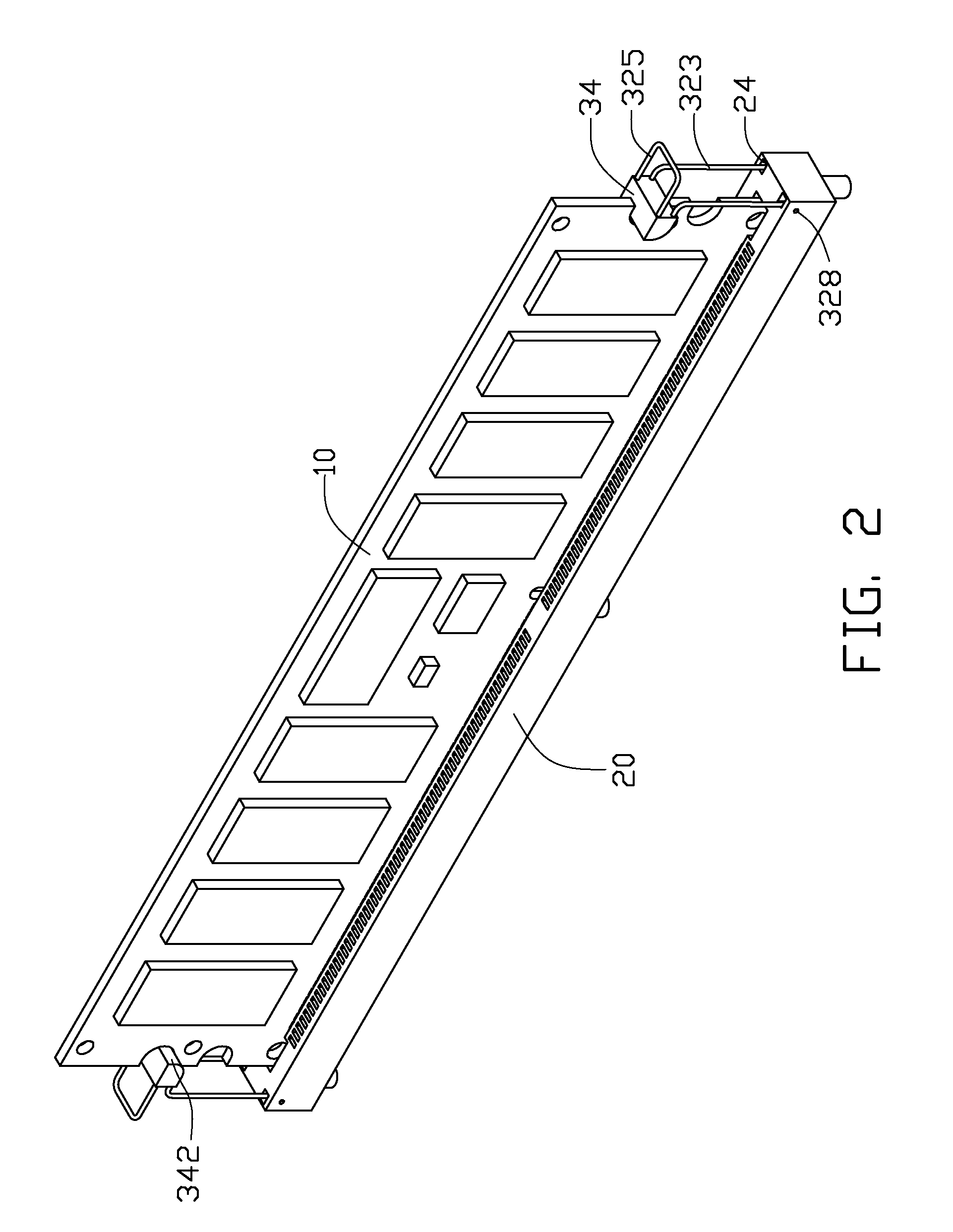
[0008]Referring to FIG. 1, an exemplary embodiment of a mounting apparatus is provided for fixing an expansion card 10. The mounting apparatus includes a connector 20 installable on a circuit board (not shown), and two latching members 30.

[0009]A plurality of horizontally spaced pins 12 are formed on a bottom portion of the expansion card 10. The expansion card 10 includes two opposite ends, and an arc-shaped recess 14 defined in each end.

[0010]The connector 20 is elongated. The connector 20 includes a top surface 21 and two sidewalls 23 perpendicular to the top surface 21. The connector 20 further includes two opposite end portions. The top surface 21 defines two slots 22 arranged in a line between the end portions, for receiving and being electrically connected to the pins 12. Two grooves 24 are defined in the top surface 21 adjacent each end portion. An inside wall 242 is formed in each groove 24 for bounding a side of the corresponding groove 24 away from the slots 22. An upper ...


PUM


Abstract

A mounting apparatus includes a connector for engagingly receiving a bottom portion of an expansion card, and a latching member. The latching member includes a main body and a latching portion connected to the main body for engaging an end of the expansion card. The main body is formed by a metal wire and includes two arms. A foot extends from each of the arms and is pivotably connected to the connector adjacent the end of the expansion card.

Description

BACKGROUND[0001]1. Technical Field[0002]The present disclosure relates to mounting apparatuses and, more particularly, to a mounting apparatus for an expansion card.[0003]2. Description of Related Art[0004]An expansion card such as a memory card, is installed in an electronic device, such as a computer or a server with a mounting apparatus. The mounting apparatus includes two opposite fixing plates for clamping two opposite ends of the expansion card. However, the fixing plates may block airflow to the expansion card. In a chassis having a plurality of expansion cards fixed in parallel, heat produced by the expansion cards can only be dissipated through the narrow spaces between the cards, which is inefficient.BRIEF DESCRIPTION OF THE DRAWINGS[0005]FIG. 1 is an exploded, isometric view of an exemplary embodiment of a mounting apparatus, together with an expansion card.[0006]FIG. 2 is an assembled view of the mounting apparatus and the expansion card of FIG. 1.[0007]FIG. 3 is similar...

Claims


Application Information

Patent Timeline
IPC IPC(8): H01R13/62
CPCH05K7/1431H01R12/7005H01R12/721
Inventor SUN, ZHENG-HENG
Owner HON HAI PRECISION IND CO LTD
Why Eureka
Try Eureka