Illuminated hub pointer

a technology of illumination hub and pointer, which is applied in the direction of instruments, measurement device, measurement apparatus components, etc., can solve the problems of unsatisfactory light leakage and distract from the desired appearan

Active Publication Date: 2010-02-23
CONTINENTAL AUTOMOTIVE SYST INC
View PDF14 Cites 15 Cited by
  • Summary
  • Abstract
  • Description
  • Claims
  • Application Information

AI Technical Summary

Problems solved by technology

Disadvantageously, directing light through the shaft of the pointer can create an undesired leakage of light that distracts from the desired appearance.

Method used


Image

  • Illuminated hub pointer
  • Illuminated hub pointer
  • Illuminated hub pointer

Examples


Embodiment Construction

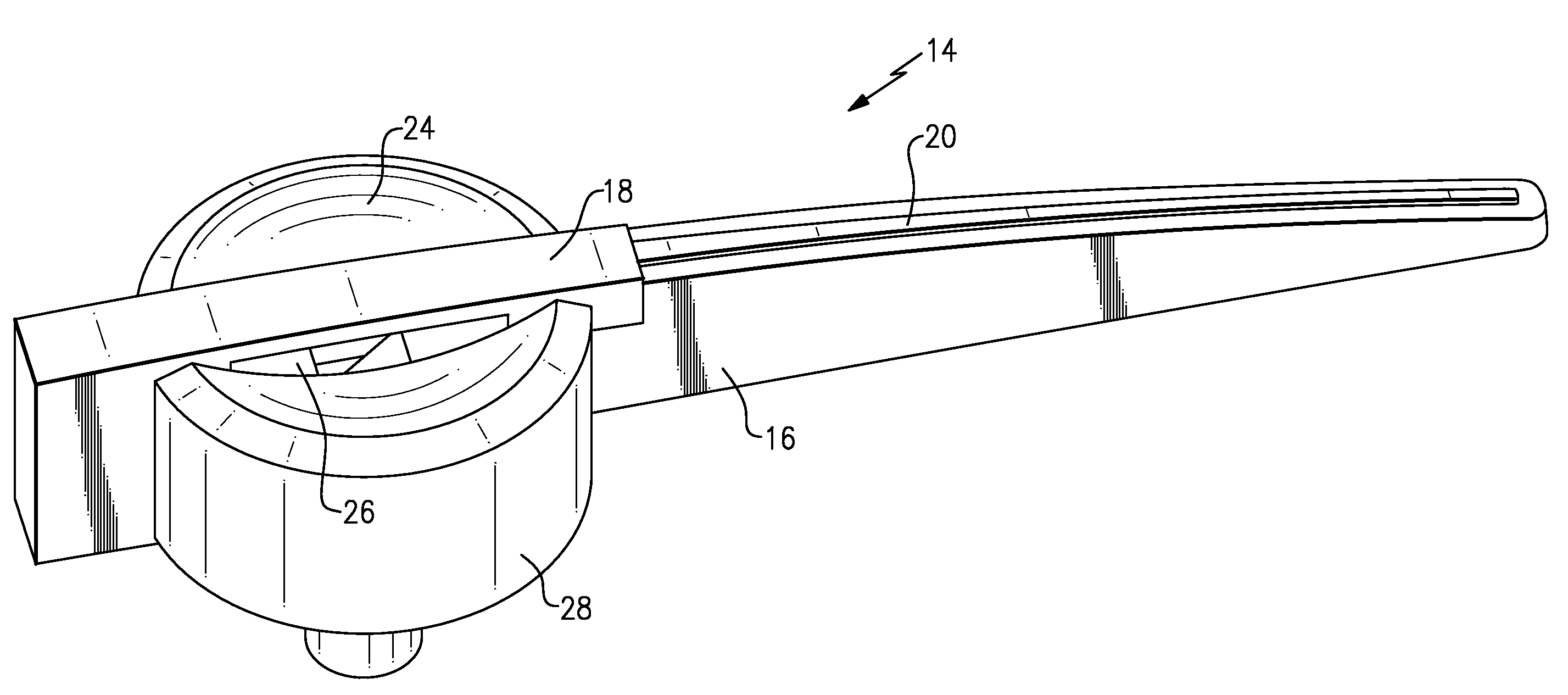
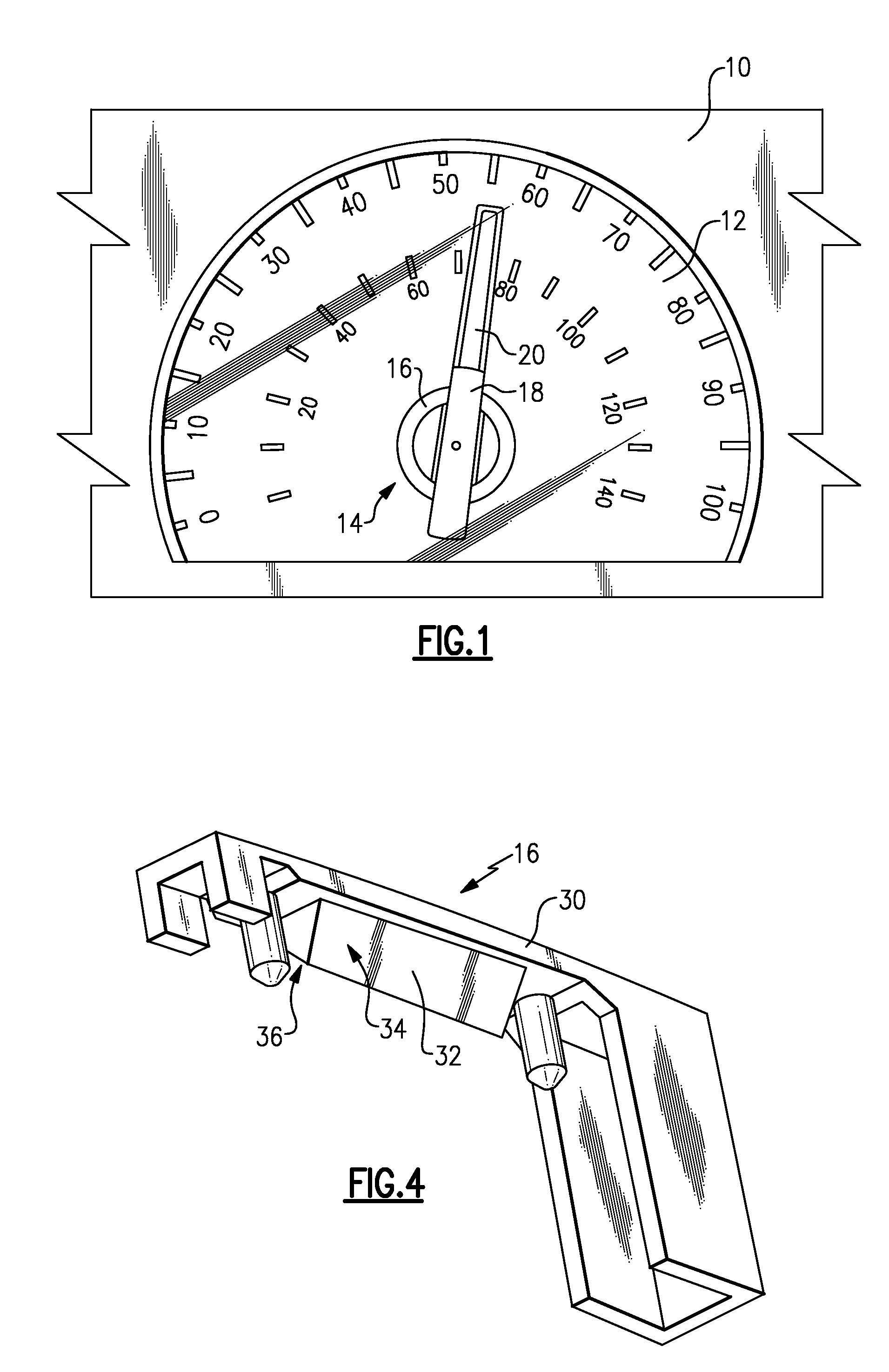
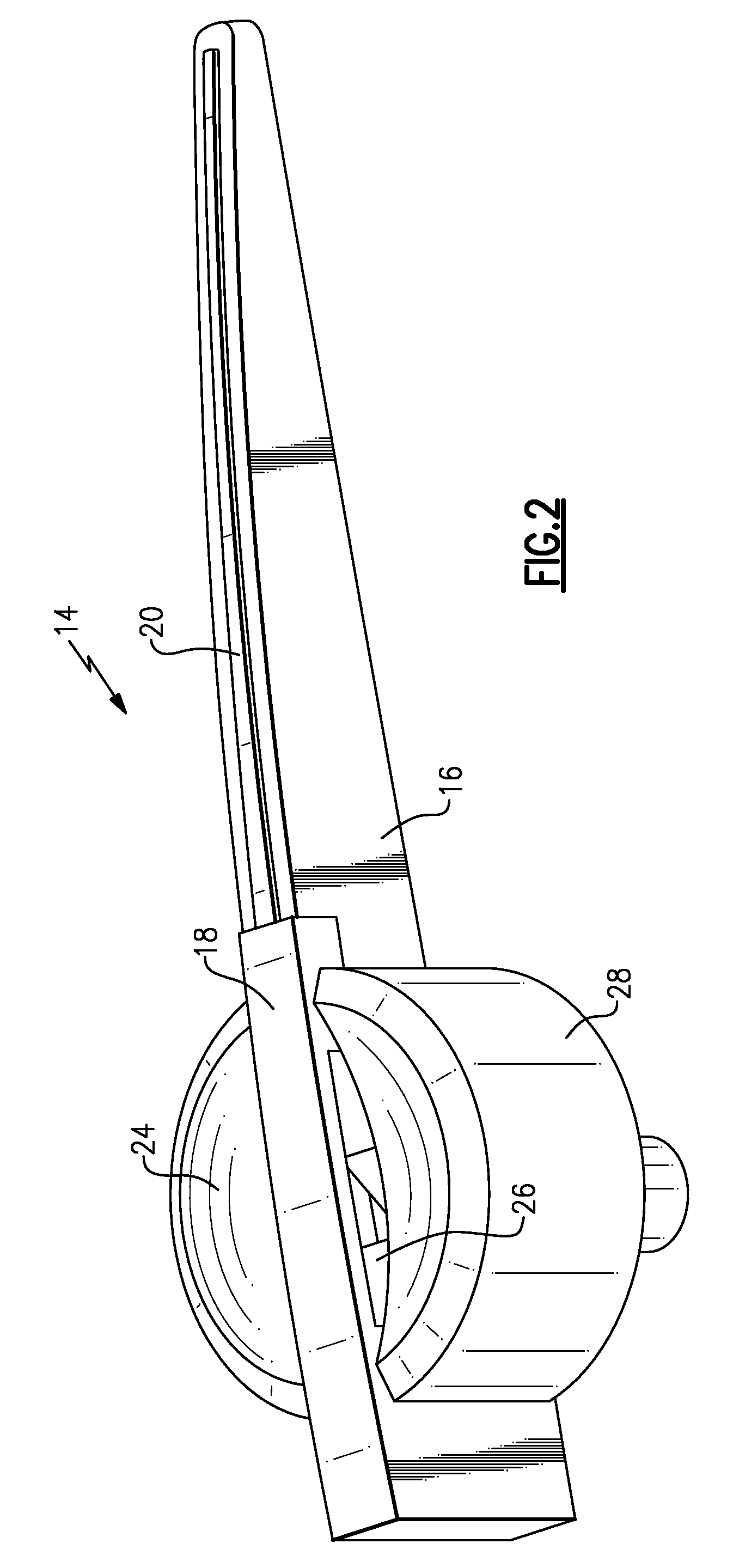
[0015]Referring to FIG. 1, an instrument panel 10 includes a gauge 12 for visibly displaying a vehicle operational parameter, such as in this example vehicle speed. Other gauges providing other vehicle operating parameters such as engine speed, temperature, pressure and other desired characteristics will also benefit from this disclosure. A pointer assembly 14 moves relative to the gauge 12 and includes graduated reference indicators to visibly communicate information to a driver. The pointer assembly 14 includes a hub 16 and an illuminated pointer 20. The pointer 20 and hub 16 are both selectively illuminated to provide a desired appearance.

[0016]Referring to FIGS. 2 and 3, the pointer assembly 14 includes the pointer 20 and hub 24 that are both illuminatable. A lower hub 22 provides a bottom shroud to block light leakage in an undesired direction. The hub 16 includes a main portion 28 with a concave surface 24. The concave surface 24 includes a slot 26. A reflector 18 is partially...


PUM


Abstract

A pointer assembly includes the pointer and hub that are both illuminatable. The hub includes a main portion with a concave surface. A reflector is partially received within a slot through the concave surface and is supported on top of the hub. The reflector includes a reflective surface that directs light onto the concave surface. Light from a light source is directed by separate reflective surfaces on the pointer and the reflector to illuminate both the hub and the pointer.

Description

CROSS REFERENCE TO RELATED APPLICATION[0001]The application claims priority to U.S. Provisional Application No. 60 / 926,486 which was filed on Apr. 27, 2007.BACKGROUND OF THE INVENTION[0002]This disclosure relates to an illuminated pointer for a vehicle instrument panel.[0003]A vehicle instrument gauge or cluster includes a pointer for indicating a parameter indicative of vehicle operation or condition. The pointer may be illuminated to enhance instrument cluster appearance. The pointer is typically illuminated by directing light onto reflective surfaces within the pointer. The light can be directed through an axis or shaft into the pointer. Disadvantageously, directing light through the shaft of the pointer can create an undesired leakage of light that distracts from the desired appearance. Hubs or shrouds are utilized to block this leakage of light; however, some light remains visible.[0004]Accordingly, it is desirable to design and develop an illuminated pointer that provides a de...

Claims


Application Information

Patent Timeline
Patent Type & Authority Patents(United States)
IPC IPC(8): G01D11/28G12B11/04
CPCG01D11/28Y10S116/36Y10S116/06
Inventor BIRMAN, VYACHESLAV B.TANGUY, CHRISTIAN
Owner CONTINENTAL AUTOMOTIVE SYST INC
Why Eureka
Try Eureka