Steam heated vulcanization apparatus

a technology of steam heating and vulcanizing apparatus, which is applied in the direction of dough shaping, manufacturing tools, other domestic objects, etc., can solve the problems of time-consuming operation, difficult to handle beams, and additional expenses incurred in paying the operator of such devices

Inactive Publication Date: 2010-02-23
PRICE JOHN G
View PDF4 Cites 1 Cited by
  • Summary
  • Abstract
  • Description
  • Claims
  • Application Information

AI Technical Summary

Benefits of technology

[0021]It is a further object of the present invention to provide a lightweight portable steam vulcanizing device which enables the use of steam so as to provide both pressure and heat for the vulcanization process.
[0022]It is a yet further object of the present invention to provide a lightweight portable steam vulcanizing device which enables the cooling of the vulcanized area without the use of additional equipment and while avoiding blistering of the splice.
[0023]It is a still further object of the present invention to provide a lightweight portable steam vulcanizing device which enables a smooth transition between the original material and newly vulcanized material for esthetic purposes. It is a still further object of the present invention to provide a lightweight portable steam vulcanizing device which enables the operator thereof to vulcanize a spliced area of a rubber belt with great efficiency and economy.
[0025]The platens of the steam heated vulcanization apparatus comprise a rigid metal outer plate, a flexible metal inner sheet, spacers between the outer plate and the inner sheet defining a steam chamber, an inlet port releasably connectable to a steam source, and a plurality of apertures through the outer plate and the inner sheet to receive connecting bolts therethrough, the apertures having seal means whereby steam is prevented from escaping from the steam chamber.

Problems solved by technology

Thus, in known systems, there has always been a problem with coordinating the source of pressurization with the source of heating so as to properly vulcanize the belt ends to form a proper joint.
In order to produce the required surface pressure at the area of the splice using screw clamping, it is necessary to tighten the clamp to a predetermined torque which requires expensive torque-measuring devices with the further expense incurred for paying the operator of such devices.
In such an operation, a large number of screw clamps may be necessary so as to properly pressurize the entire surface area, and accordingly, it is a time consuming operation to ensure that each clamp carries its correct load.
A further problem arises from the fact that the screw clamps may only be placed along the outer edges of the belt, thus necessitating the use of transverse beams of great rigidity so as to evenly spread the pressure created by the torquing-down of the screw clamps across the surface of the splice.
In order to provide sufficient rigidity in the beam so as to perform its required function, such a beam must be made quite heavy and accordingly such a beam is quite difficult to handle.
The major drawback to the use of a rubber bag is that, due to the fact that the region wherein the rubber bag is utilized is also heated to high temperatures, the lifespan of such a rubber bag is extremely limited.
Further, replacing such a rubber bag is extremely expensive.
The main drawback to the use of electricity as a source of heat is that the site where the splicing is to take place must be within close proximity of a suitable power supply for the electricity or otherwise a large, expensive mobile electrical generator must be provided.
Also, the heaters required to generate the temperatures required for vulcanization require significant voltage and, in most instances, the use of extremely long extension cables are necessary which results in large losses in voltage which thereby lowers the temperatures which may be provided through an electrical source.
The main limitation to the use of steam appears to be the requirement for a separate boiler arrangement so as to provide the steam.
However, even steam heat requires the application of pressure evenly across the area being vulcanized.
In one embodiment, nails are inserted through the ends of the belt and splice material to hold the ends together during vulcanization, but the nails provide no clamping function.
In any event, there is no means disclosed in this patent to permit the use of steam to provide heat or pressure for vulcanization in a portable apparatus.

Method used


Image

  • Steam heated vulcanization apparatus
  • Steam heated vulcanization apparatus
  • Steam heated vulcanization apparatus

Examples


Embodiment Construction

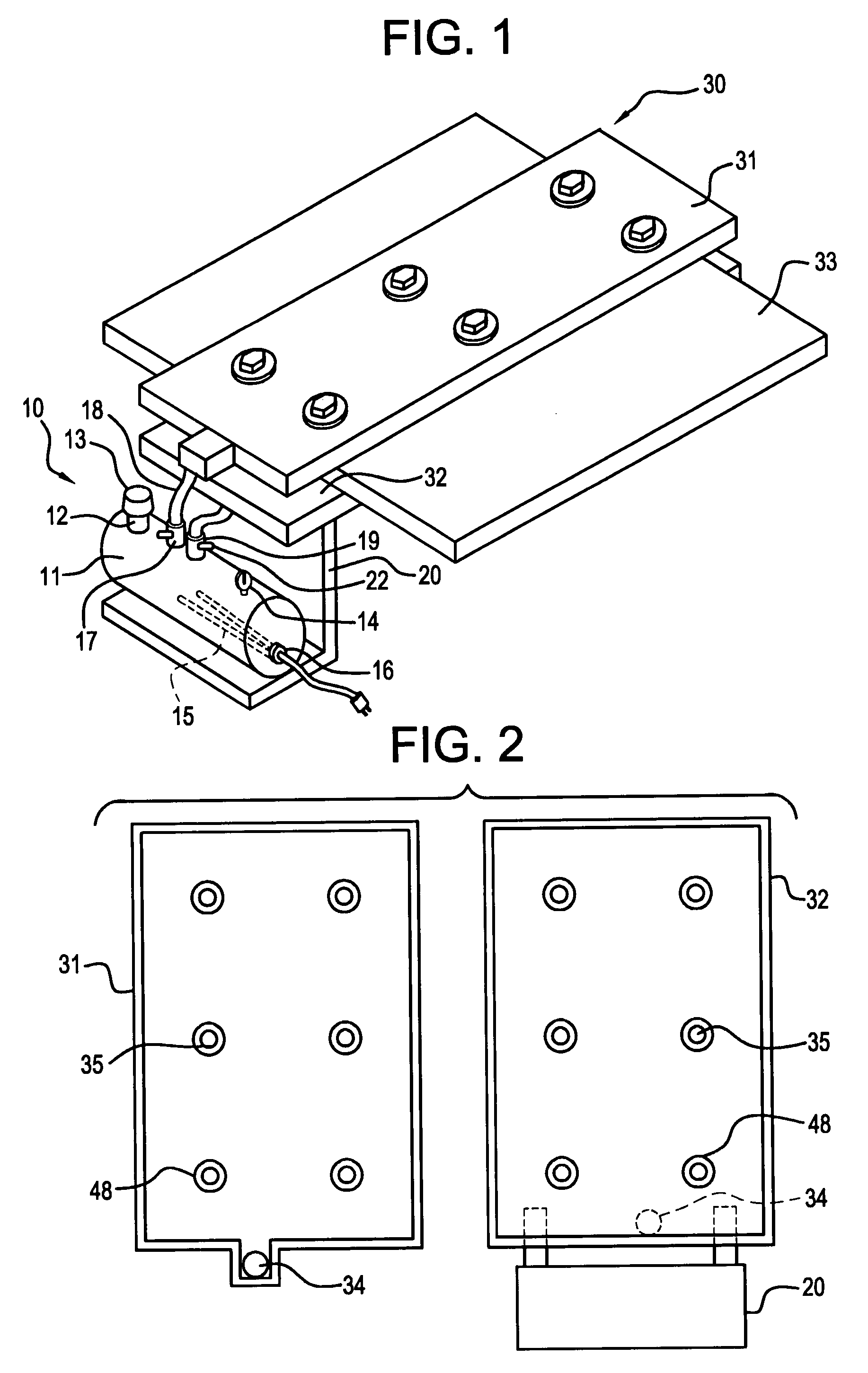
[0033]Referring now to FIG. 1, the apparatus embodying the present invention includes a steam supply system 10 and a vulcanizing apparatus 30. The steam supply system 10 may be provided as an integral element as shown or it may be separate from the vulcanizing apparatus 30.

[0034]The steam supply system 10 includes a boiler 11 in which is contained a predetermined amount of water. A filler port 12 including an overpressure safety release valve 13 is provided for introduction of water to the boiler 11. The overpressure safety release valve is calibrated to open at a pressure higher than that required by the vulcanizing apparatus 30 but lower than that which would result in rupture of the boiler 11 or other components of the steam supply system 10 or the vulcanizing apparatus 30. A pressure gauge 14 provides the operator with a visual display of the steam pressure in the boiler 11.

[0035]Heat to convert the water to steam is preferably provided by immersible electrically operated calrod...


PUM

PropertyMeasurementUnit
pressureaaaaaaaaaa
pressureaaaaaaaaaa
thicknessaaaaaaaaaa

Abstract

Disclosed herein is an apparatus for vulcanizing rubber, particularly for vulcanizing the ends of endless rubber belts. The apparatus disclosed herein is a lightweight and portable steam heated vulcanization apparatus which comprises upper and lower platens comprising hollow bodies having a rigid outer wall and a flexible inner wall and adapted to receive steam therein and transmit heat and pressure to a rubber belt placed between the flexible inner walls of the platens. A steam source is connected to the platens for delivery of steam and a plurality of connecting bolts pass through apertures in the platens and the belt material therebetween to align the platens and secure them together so as to apply pressure to the belt in combination with heat for optimal vulcanization.

Description

FIELD OF THE INVENTION[0001]This invention relates to a steam vulcanizing apparatus which eliminates the need for heavy and bulky frames or complex hydraulic and pneumatic presses to apply and contain the pressure required for vulcanizing rubber. Utilizing modified steam platens adapted to receive connecting means which pierce the rubber sections being vulcanized, the present invention provides a steam vulcanizing apparatus that is sufficiently portable so as to be easily transported and used in the field for the manufacture or repair of rubber belts.BACKGROUND OF THE INVENTION[0002]In order to join the two ends of a rubber belt together and in the process provide a strong joint therebetween, it is necessary to provide the proper heat and pressure simultaneously at the region of the joint which heat and pressure, when properly applied, act to vulcanize the rubber and thereby bond the belt ends together to form a joint. Often, in order to strengthen the joint, rubber cement is used a...

Claims


Application Information

Patent Timeline
Patent Type & Authority Patents(United States)
IPC IPC(8): B29C35/04
CPCB29C35/049B29C66/4324B29C65/18B29C65/26B29C66/1122B29C66/43B29D29/00B29C65/305B29C65/00B29C66/128B29C66/855B29K2021/00B29L2031/7092B29C35/06B29C66/1282B29C66/12841B29C66/71
Inventor PRICE, JOHN G.
Owner PRICE JOHN G
Why Eureka
Try Eureka