Apparatus and method of motion-compensation adaptive deinterlacing

a technology of adaptive deinterlacing and adaptive deinterlacing, applied in the field of apparatus and method of motion compensatory deinterlacing, can solve the problems of inability to take full advantage of given information, difficulty in realizing the hardware configuration for extracting motion information, and inferior output image quality of the conventional motion adaptive deinterlacing algorithm to that of the conventional motion compensatory deinterlacing algorithm. achieve the effect of optimal image quality

Inactive Publication Date: 2010-02-23
IND ACAD COOP GRP OF SEJONG UNIV +1
View PDF39 Cites 35 Cited by
  • Summary
  • Abstract
  • Description
  • Claims
  • Application Information

AI Technical Summary

Benefits of technology

[0013]The present general inventive concept provides an apparatus and method of motion-compensation adaptive deinterlacing, in which motion adaptive deinterlacing is used when there is no motion in an image and motion-compensation deinterlacing is used when there is horizontal motion or a vertical slow motion in an image, thereby providing optimal image quality.

Problems solved by technology

However, in the case of a still image, since this algorithm provides an image quality that is inferior to the conventional motion adaptive deinterlacing algorithm or the conventional motion-compensation deinterlacing algorithm, it is usually combined with the conventional motion adaptive deinterlacing algorithm or the conventional motion-compensation deinterlacing algorithm in HD digital TV applications.
However, when there is a motion in an image, the output image quality of the conventional motion adaptive deinterlacing algorithm is inferior to that of the conventional motion-compensation deinterlacting algorithm.
Moreover, since a pixel should be synthesized only using information within a frame, if there is a little motion, it is impossible to take full advantage of given information.
However, the actual hardware configuration for extracting motion information is difficult to implement.
Moreover, since inaccurate motion estimation directly leads to quality degradation, it is not easy to use the conventional motion-compensation deinterlacing algorithm in actual applications.

Method used


Image

  • Apparatus and method of motion-compensation adaptive deinterlacing
  • Apparatus and method of motion-compensation adaptive deinterlacing
  • Apparatus and method of motion-compensation adaptive deinterlacing

Examples


Embodiment Construction

[0025]Reference will now be made in detail to the embodiments of the present general inventive concept, examples of which are illustrated in the accompanying drawings, wherein like reference numerals refer to the like elements throughout. The embodiments are described below in order to explain the present general inventive concept while referring to the figures.

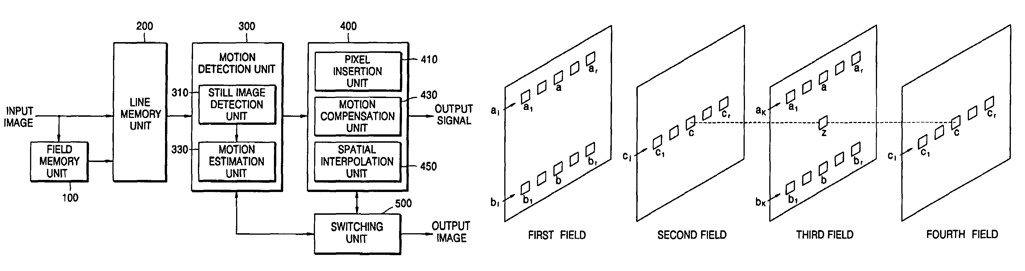
[0026]FIG. 2 is a block diagram illustrating a motion-compensation adaptive deinterlacing apparatus according to an embodiment of the present general inventive concept.

[0027]Referring to FIG. 2, the motion-compensation adaptive deinterlacing apparatus includes a field memory unit 100, a line memory unit 200, a motion detection unit 300, an interpolation unit 400, and a switching unit 500. The motion detection unit 300 includes a still image detection unit 310 and a motion estimation unit 330. The interpolation unit 40 includes a pixel insertion unit 410, a motion compensation unit 430, and a spatial interpolation unit 450.

[00...


PUM


Abstract

An apparatus and method of motion-compensation adaptive deinterlacing. The method includes detecting whether an input image is a still image using information regarding the input image stored in a memory, estimating a motion of a pixel to be interpolated when the input image is not a still image, and interpolating the pixel to be interpolated using one of using pixel values of previous and next fields with respect to a reference field including the pixel to be interpolated when the input image is the still image, the estimated motion information when the input image is not the still image and has no vertical fast motion, and pixel values of the reference field when the input image has a vertical fast motion.

Description

CROSS-REFERENCE TO RELATED APPLICATIONS[0001]This application claims the benefit under 35 U.S.C. § 119 of Korean Patent Application No. 2004-59062, filed on Jul. 28, 2004, in the Korean Intellectual Property Office, the disclosure of which is incorporated herein in its entirety by reference.BACKGROUND OF THE INVENTION[0002]1. Field of the Invention[0003]The present general inventive concept relates to an apparatus and method of motion-compensation adaptive deinterlacing, and more particularly, to an apparatus and method of motion-compensation adaptive deinterlacing in which motion adaptive deinterlacing and motion-compensation deinterlacing are combined to convert interlaced video into progressive scan video.[0004]2. Description of the Related Art[0005]The recent development of digital TV technology and large-screen display devices, such as plasma digital panel (PDP) TVs and projection TVs using digital lighting processing (DLP), liquid crystal display (LCD), and liquid crystal on s...

Claims


Application Information

Patent Timeline
Patent Type & Authority Patents(United States)
IPC IPC(8): H04N7/01G06K9/40H04N9/64H04N5/14
CPCH04N5/145H04N7/012H04N7/01G06T7/20
Inventor HAN, DONGIL
Owner IND ACAD COOP GRP OF SEJONG UNIV
Why Eureka
Try Eureka