Manually adjustable outrigger

a man-made, outrigger technology, applied in fishing, special-purpose vessels, machine supports, etc., can solve the problems of reduced overall clearance to overhead obstacles, present difficulties in navigation, and inability to meet the requirements of boat clearan

Active Publication Date: 2010-03-02
EASTERN METAL SUPPLY
View PDF92 Cites 27 Cited by
  • Summary
  • Abstract
  • Description
  • Claims
  • Application Information

AI Technical Summary

Benefits of technology

[0017]A bayonet coupler concentric with the piston causes the piston to rotate as it moves vertically within the coupler. The coupler is provided with a parallel pair of inclined tracks cut into the cylindrical face of the coupler. Guide pins attached to bottom of the piston ride in the tracks of the bayonet coupler, causing the piston to rotate about its vertical axis as it moves upwards.

Problems solved by technology

The deployed position of the outrigger pole can present difficulties during navigation.
The elevated pole position reduces the overall clearance to overhead obstacles, such as bridges.
When navigating the fishing vessel in narrow waters, the required clearance around the boat may not be available.
It is desirable that an outrigger firmly maintain the position of the trolling pole in both the stowed and the deployed condition so that the pole does not swing about, thus presenting a hazard to personnel aboard the vessel.

Method used


Image

  • Manually adjustable outrigger
  • Manually adjustable outrigger
  • Manually adjustable outrigger

Examples


Embodiment Construction

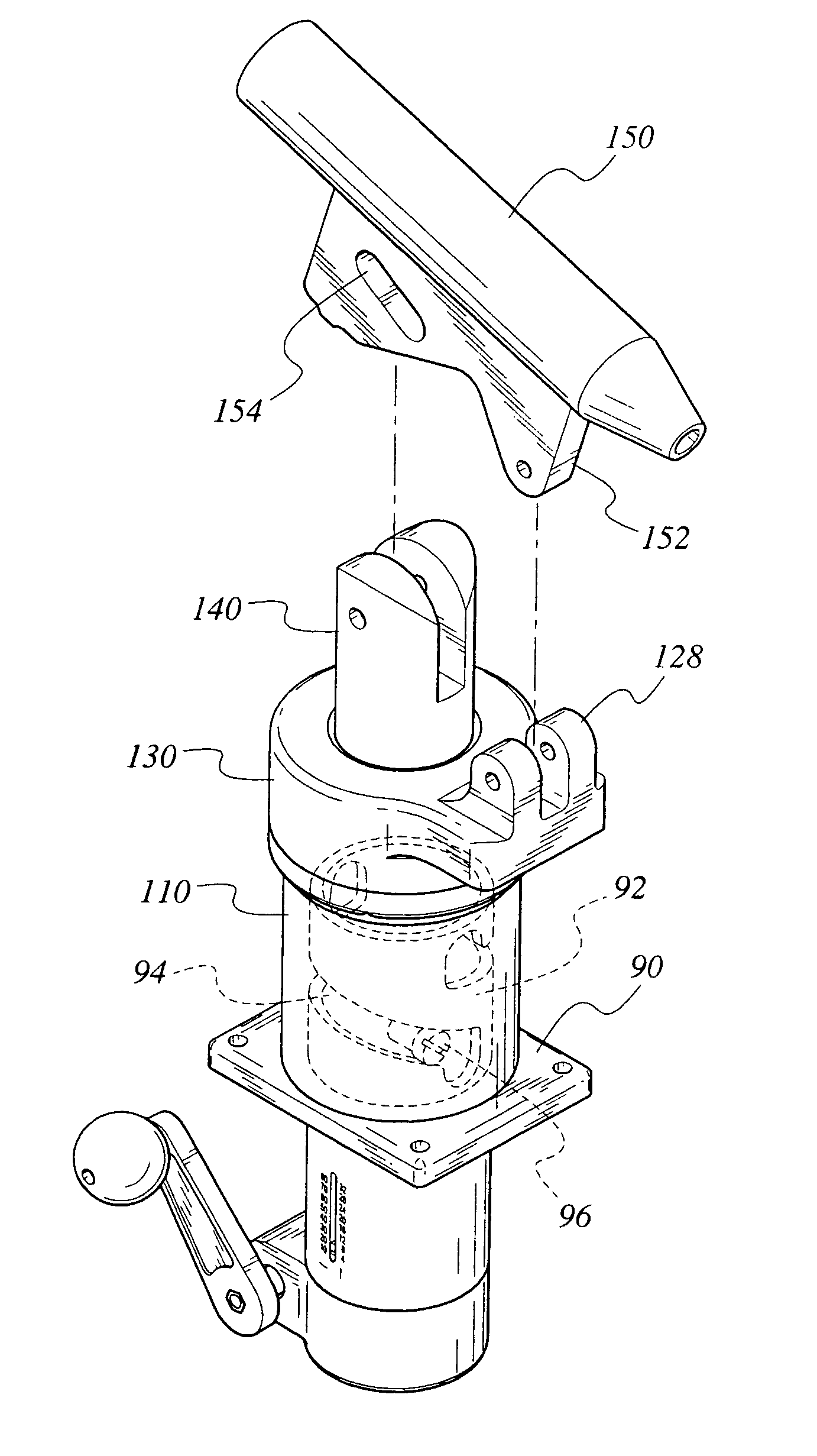
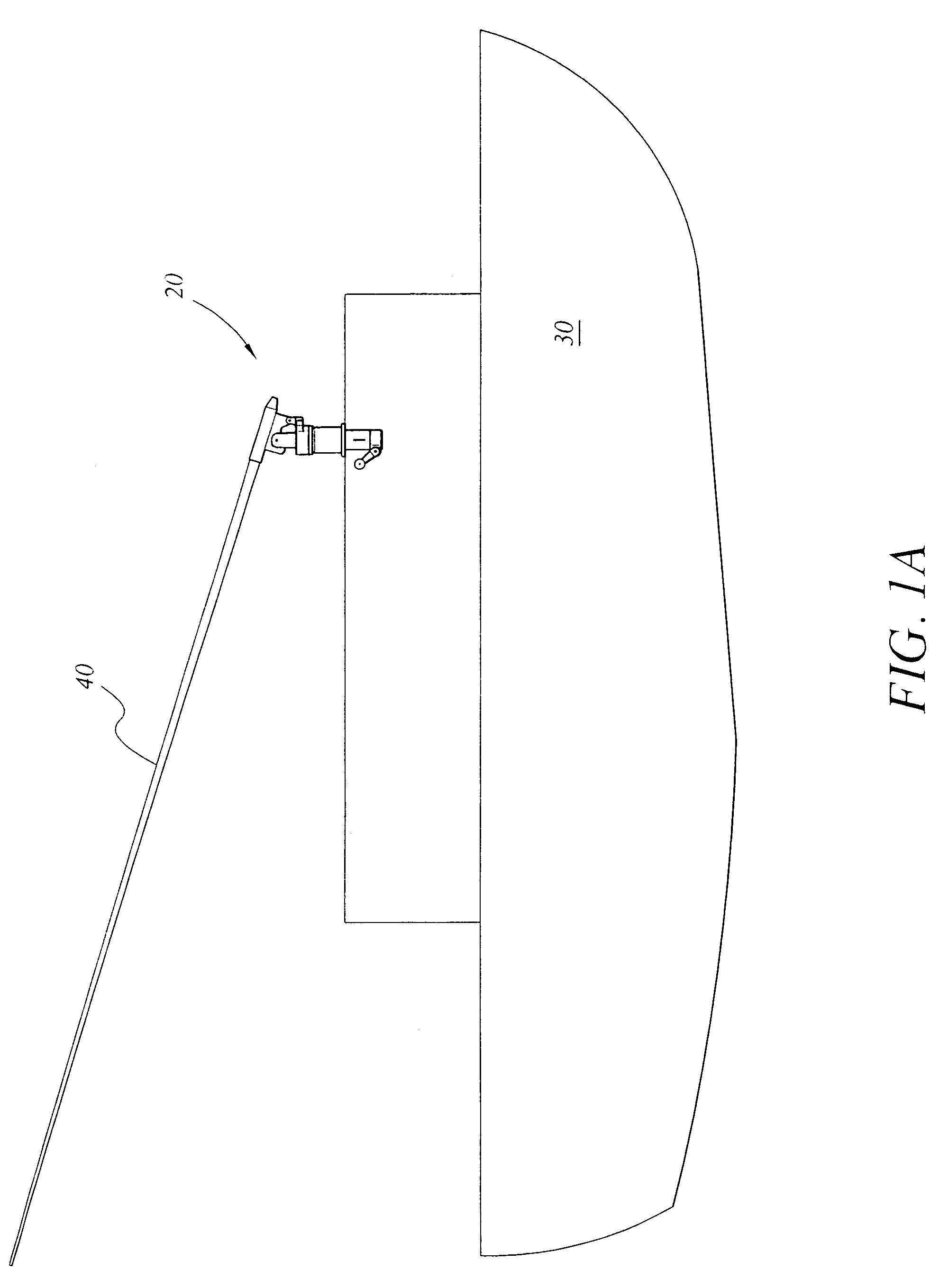
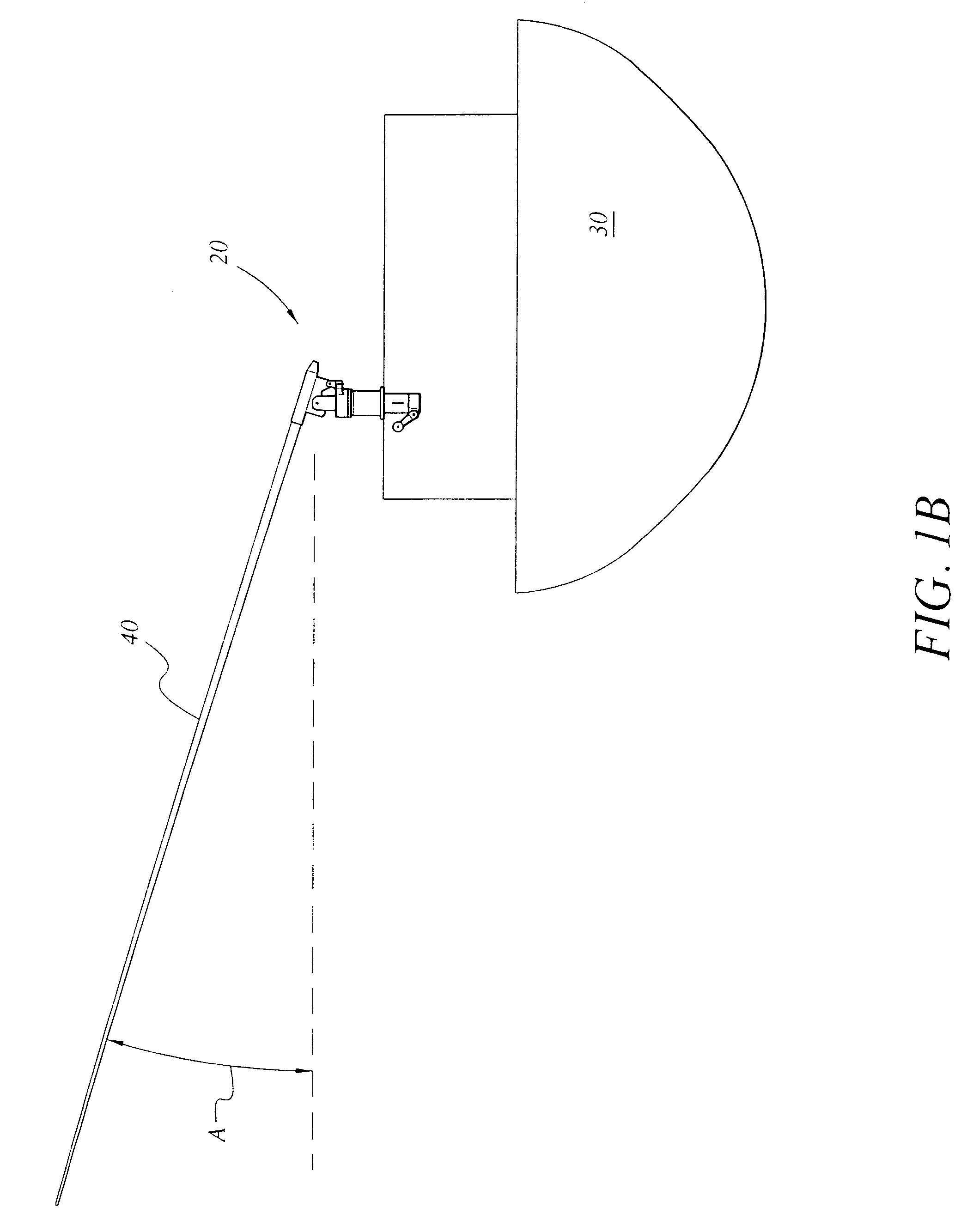
[0030]A preferred embodiment of an adjustable outrigger 20, namely, a manually adjustable embodiment, is shown attached to a fishing boat in FIGS. 1A-1C. The outrigger 20 is mounted to the top of the fishing boat 30. The outrigger 20 holds a trolling pole 40. By rotating the outrigger 20, the pole 40 may be rotated into the desired position. FIGS. 1A and 1B show the outrigger 20 holding the pole 40. FIG. 1B shows the outrigger 20 holding pole 40 in a deployed position. In the deployed position, the pole 40 is elevated at a relatively high angle, and the trolling pole 40 is positioned outboard of the boat 30. In FIG. 1C, the outrigger 20 holds the trolling pole 40 in a stowed position inboard of the boat 30. The elevation angle of the pole 40 is reduced to a more nearly horizontal position, providing a more compact arrangement of the pole 40 when not in use. By rotating the operating handle 62 (see FIG. 2) of the outrigger 20, the pole 40 may be moved from the deployed position to th...


PUM


Abstract

An adjustable outrigger moves a trolling pole on a fishing vessel to an elevated, outboard position for trolling and inboard to a lowered position when not in use. The outrigger of a preferred embodiment is operated using an operating handle. Rotating the operating handle in one direction rotates a pole held by the outrigger from an inboard position to the outboard, deployed position. Simultaneously with the rotation in the horizontal plane, the pole is elevated in the vertical plane from a near horizontal position to a suitable trolling angle. The operating handle turns a shaft that communicates the rotation of the handle to an internal drive mechanism, which is housed in a drive mechanism housing. The rotational motion is converted to a linear, vertical action using a ball gear mechanism. A track provided by a bayonet coupler converts the linear vertical motion into a combined vertical and rotational motion.

Description

CROSS-REFERENCE TO RELATED APPLICATION[0001]This application claims the benefit of U.S. Provisional Patent Application Ser. No. 60 / 736,857, filed Nov. 16, 2005.FIELD OF THE INVENTION[0002]The present invention relates to fishing equipment in general, and in particular to an adjustable outrigger for extending trolling lines outboard of a boat.DESCRIPTION OF THE RELATED ART[0003]Trolling is a popular fishing technique. Trolling involves trailing a baited line and hook behind a slowly moving fishing boat. The slow motion of the boat causes the trolled bait to simulate the movement of a slow swimming prey, making the bait attractive to predator fish. Ideally, the predator fish will strike (attempt to bite) the bait in anticipation of obtaining an easy meal and will become hooked.[0004]A fisherman can increase the number of strikes by trolling multiple lines from the boat simultaneously. When trolling with multiple lines, it is desirable to keep the lines spatially separated behind the b...

Claims


Application Information

Patent Timeline
Patent Type & Authority Patents(United States)
IPC IPC(8): A01K97/10
CPCA01K91/08
Inventor BAEZ, LAUDELINO
Owner EASTERN METAL SUPPLY
Why Eureka
Try Eureka