
Muffler for vehicle

a technology for mufflers and vehicles, applied in the field of mufflers for vehicles, can solve the problems of increasing investment costs, complex manufacturing process of mufflers, and increasing manufacturing costs of vehicles, so as to reduce molding and manufacturing costs, prevent vibration or noise of mufflers, and reduce the effect of manufacturing costs

Active Publication Date: 2010-03-02
HYUNDAI MOTOR CO LTD
View PDF25 Cites 8 Cited by
  • Summary
  • Abstract
  • Description
  • Claims
  • Application Information

AI Technical Summary

Benefits of technology

The present invention provides a muffler for a vehicle that can prevent noise and vibration by integrating a housing with baffles, which can be used for various types and engines of vehicles. This muffler can reduce manufacturing costs and development time for molds and vehicles. The muffler includes an inflow pipe and an outflow pipe that fluid-communicate with the outside, and a plurality of muffler bodies that can be fitted together to form a duel muffler. The muffler bodies have integrally formed baffles and a housing, and can be manufactured using a single mold and assembled using common tools or standards. The muffler can also be used for left and right mufflers by simply turning one muffler up / down. Overall, the present invention provides a cost-effective and efficient solution for reducing noise and vibration in vehicles.

Problems solved by technology

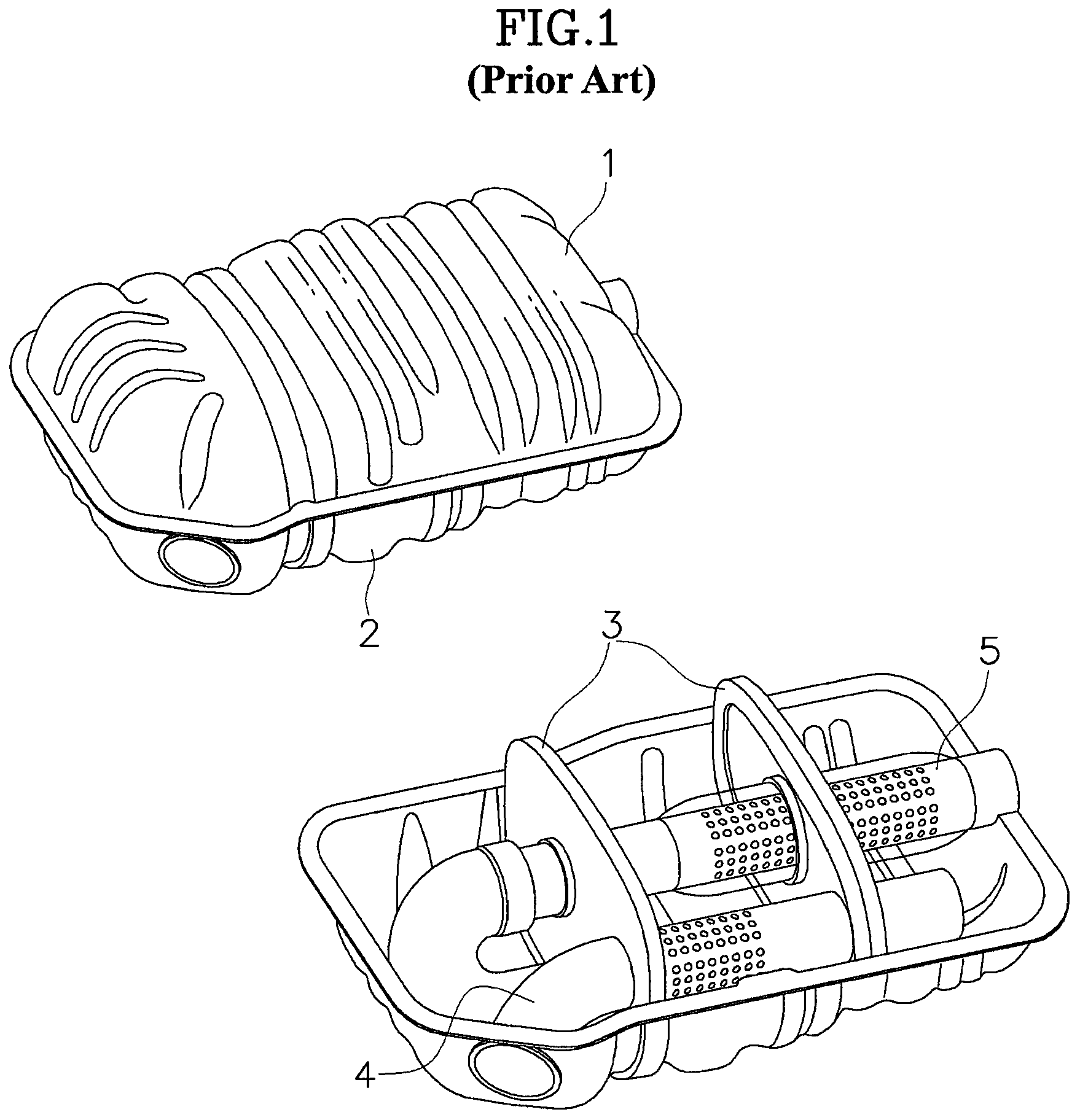
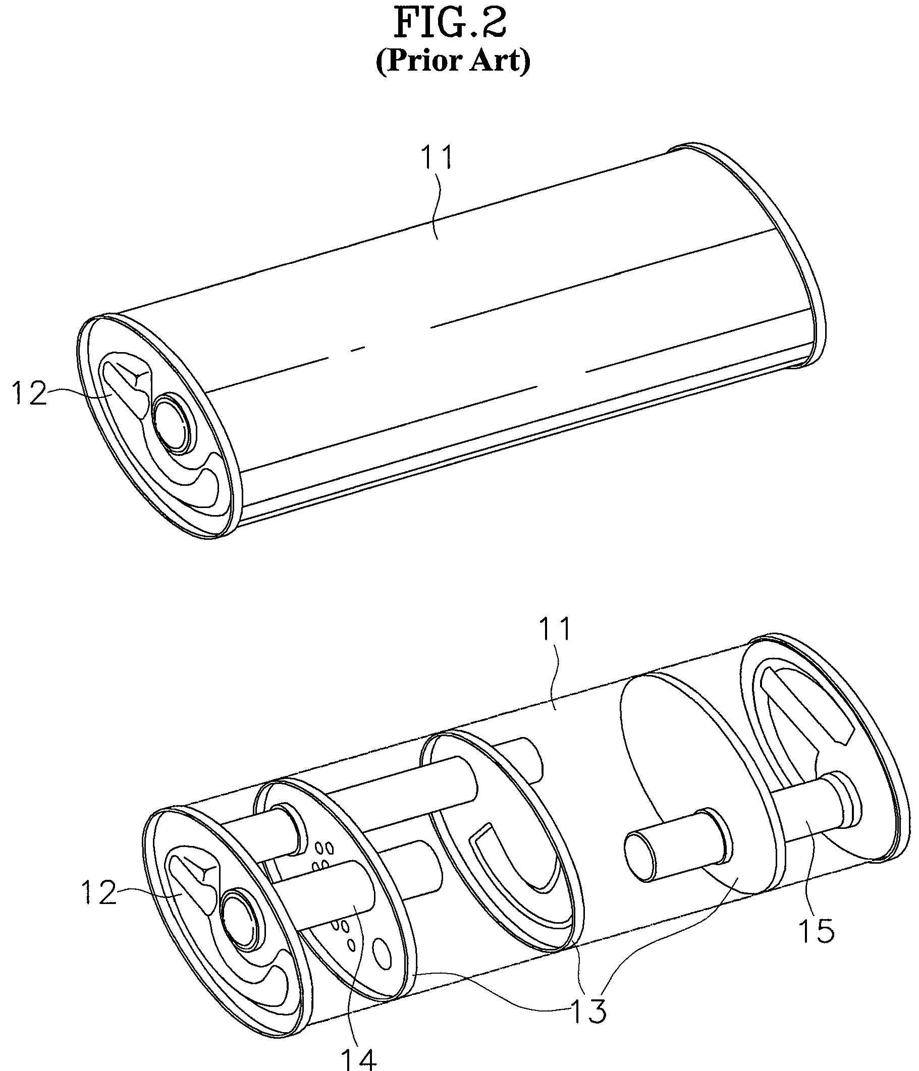
However, according to the structures of the mufflers in the related arts, there was a problem in that since the housings and baffles, which are formed of similar materials having similar thicknesses, are separately manufactured and assembled, molds for respectively manufacturing them and jigs and tools for assembling them are required, such that the manufacturing process of the mufflers is complicated and the manufacturing cost of a vehicle increases.
Further, there was a problem in that since it is required to develop new molds, depending on the capacities of the mufflers, which are different for the types and engines of vehicles, the investment cost increases.
Further, there was a problem in that the inner sides of the housings and the edges of the baffles are not in close contact with each other due to manufacturing defective of each parts or bad placement of the baffles when the housing and the baffles are assembled, such that gaps are defined and the gaps causes vibration and noise while vehicles are traveling, thereby reducing ride comfort of the vehicles.

Method used


Image

  • Muffler for vehicle
  • Muffler for vehicle
  • Muffler for vehicle

Examples


Embodiment Construction

[0039]Reference will now be made in detail to various embodiments of the present invention(s), examples of which are illustrated in the accompanying drawings and described below. While the invention(s) will be described in conjunction with exemplary embodiments, it will be understood that present description is not intended to limit the invention(s) to those exemplary embodiments. On the contrary, the invention(s) is / are intended to cover not only the exemplary embodiments, but also various alternatives, modifications, equivalents and other embodiments, which may be included within the spirit and scope of the invention as defined by the appended claims.

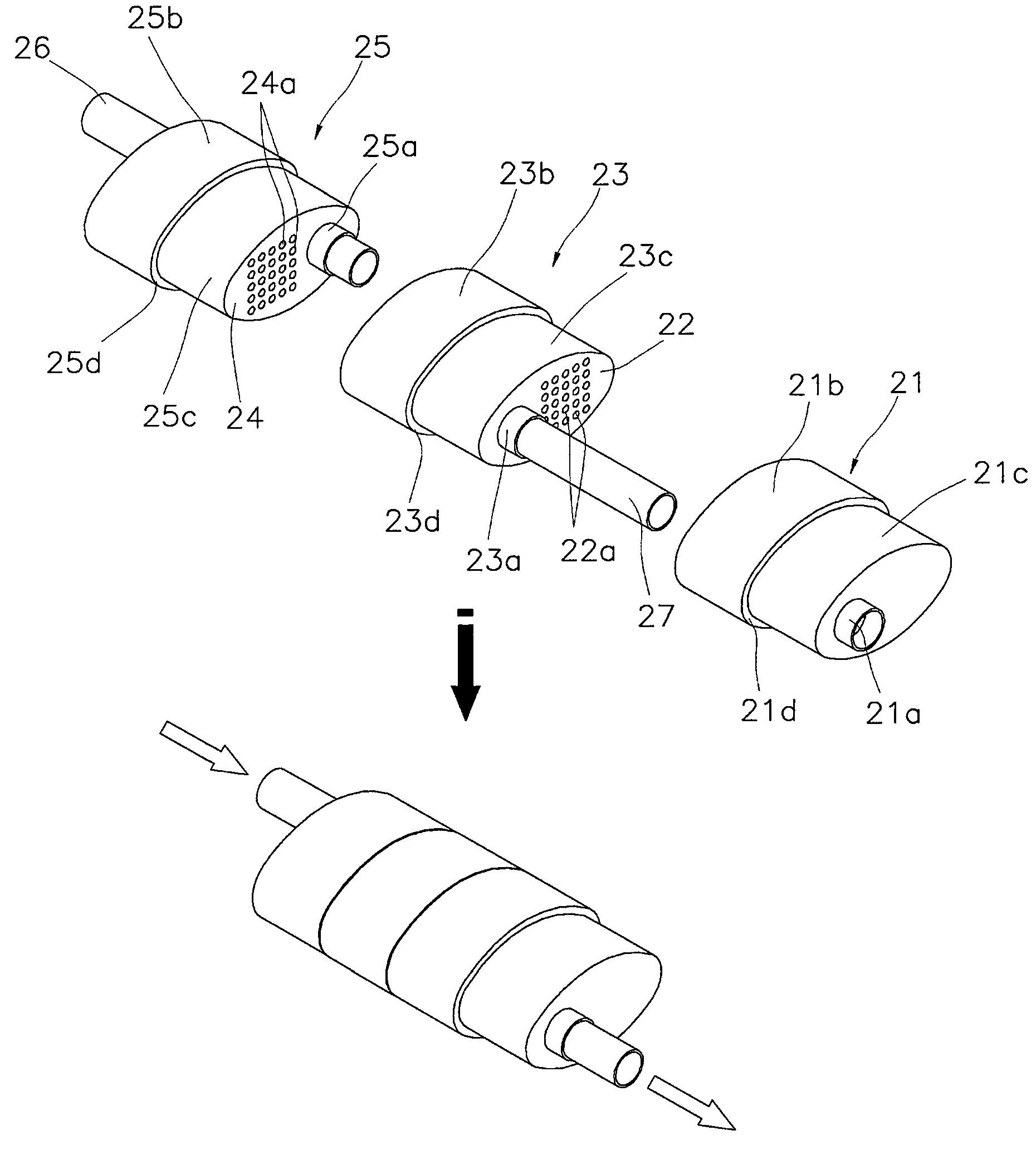
[0040]FIG. 4 is an exploded and assembled perspective view of an exemplary muffler for a vehicle according to the present invention, in which a muffler is formed by fitting a plurality of separate first, second, and third muffler bodies 21, 23, 25 to each other.

[0041]First muffler body 21 is constructed such that an opening is formed ...


PUM


Abstract

A muffler of a vehicle includes a first muffler body so as to form a first chamber, at least a second muffler body including a housing, one end portion opened and the other end portion closed, wherein one of the second muffler bodies is fitted into the other end portion of the first member to form a second chamber and the other second muffler bodies are fitted into each other through the one end portions in series to form third chambers if more than one second muffler bodies are assembled, an inflow pipe to connect the outside with the first, second and / or third chamber by passing the one end portion of the first muffler body, and an outflow pipe to communicate the first, second, and / or third chamber with the outside by passing through the other end portion of the last second muffler body.

Description

CROSS-REFERENCE TO RELATED APPLICATIONS[0001]The present application claims priority to Korean Patent Application Number 10-2008-0055263 filed Jun. 12, 2008, the entire contents of which application is incorporated herein for all purposes by this reference.BACKGROUND OF THE INVENTION[0002]1. Field of the Invention[0003]The present invention relates to a muffler for a vehicle, particularly a muffler, of which the muffler housing is integrally formed with a baffle, for a vehicle.[0004]2. Description of Related Art[0005]Mufflers for vehicles in the related art has a structure in which a plurality of chambers is formed by disposing one or more baffle in a closed housing having a predetermined volume, and an exhaust gas inflow pipe through which exhaust gas flows into the housing and an exhaust gas outflow pipe through which the exhaust gas is discharged outside the housing are disposed such that the exhaust gas flowing into the housing flows along a predetermined exhaust path in the hou...

Claims


Application Information

Patent Timeline
Patent Type & Authority Patents(United States)
IPC IPC(8): F01N1/02F01N13/18F01N1/00F01N1/08F01N13/02F01N13/08
CPCF01N1/083F01N1/084F01N1/089F01N13/18F01N13/1894F01N2470/02F01N2490/02F01N2490/08F01N1/02F01N13/08
Inventor SEON, JONGHO
Owner HYUNDAI MOTOR CO LTD
Learn More