
Folding mechanism

a folding mechanism and bicycle frame technology, applied in the direction of steering devices, frictional roller based transmission, cycle equipment, etc., can solve the problems of reducing the structural strength and resistance to compression, bending and deformation of the bicycle frame, and the joint area between the two seat tubes is not large enough to provide sufficient joining strength, so as to maximize the contact area, fold or expand, and enhance the stability of the combination

Active Publication Date: 2010-03-02
CYCLING & HEALTH TECH IND R & D CENT
View PDF15 Cites 3 Cited by
  • Summary
  • Abstract
  • Description
  • Claims
  • Application Information

AI Technical Summary

Benefits of technology

"The present invention provides a novel design of a folding bicycle frame that allows the front and rear frame members to relatively move on a pivot structure so as to make the bicycle be folded or expanded. The folding mechanism includes a combining structure positioned at the front portion of the rear frame member, at least one pivot structure, and at least one binder. The front and rear frame members are integral frame structures that maintain the structural strength and resistance to compression, bend and deformation of both frame members. The folding mechanism also positions the pivot structure at an edge of the combining structure so as to minimize the included angle between the front and rear frame members at a folded position of the frame members. The stability of combination between the frame members is enhanced by using a binder to secure the joined joining surfaces. The folding bicycle equipped with the disclosed subject matter during use can be improved in structural strength and resistance to compression, bend and deformation."

Problems solved by technology

Such design unquestionably affects the integrity of the aforementioned triangular frame and results in weakening the structural strength and resistance to compression, bend and deformation of the bicycle frame.
However, the above design may have some disadvantages.
First, since the seat tube component is constructed by concentrically placing the first seat tube inside the second seat tube, as shown in FIGS. 2A through 2D of '047 Patent, the joining area between the two seat tubes is not large enough to provide sufficient joining strength.
Such insufficient joining strength appears on the main force structure of the bicycle frame may liable to render slant and deformation of the bicycle frame.
However, since the front frame member and the rear frame member still include a relatively larger angle, the folded bicycle still consumes a relatively larger floor space for storage.

Method used


Image

  • Folding mechanism
  • Folding mechanism
  • Folding mechanism

Examples


Embodiment Construction

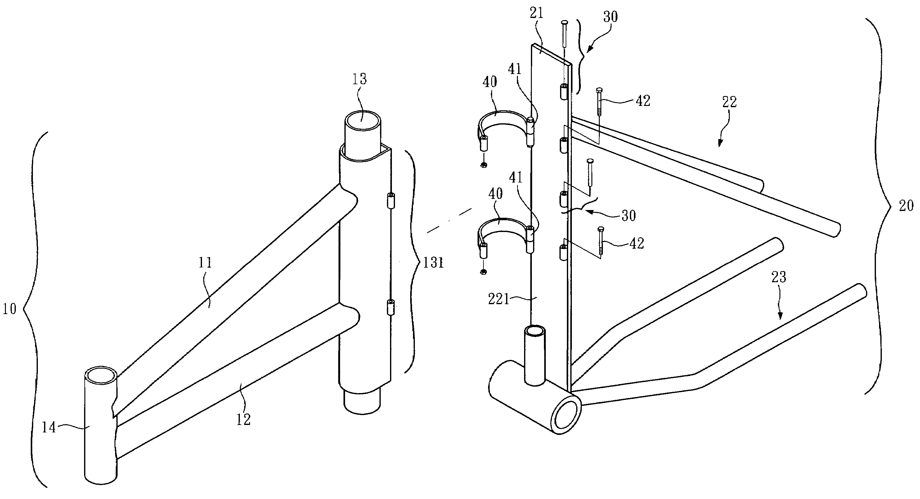
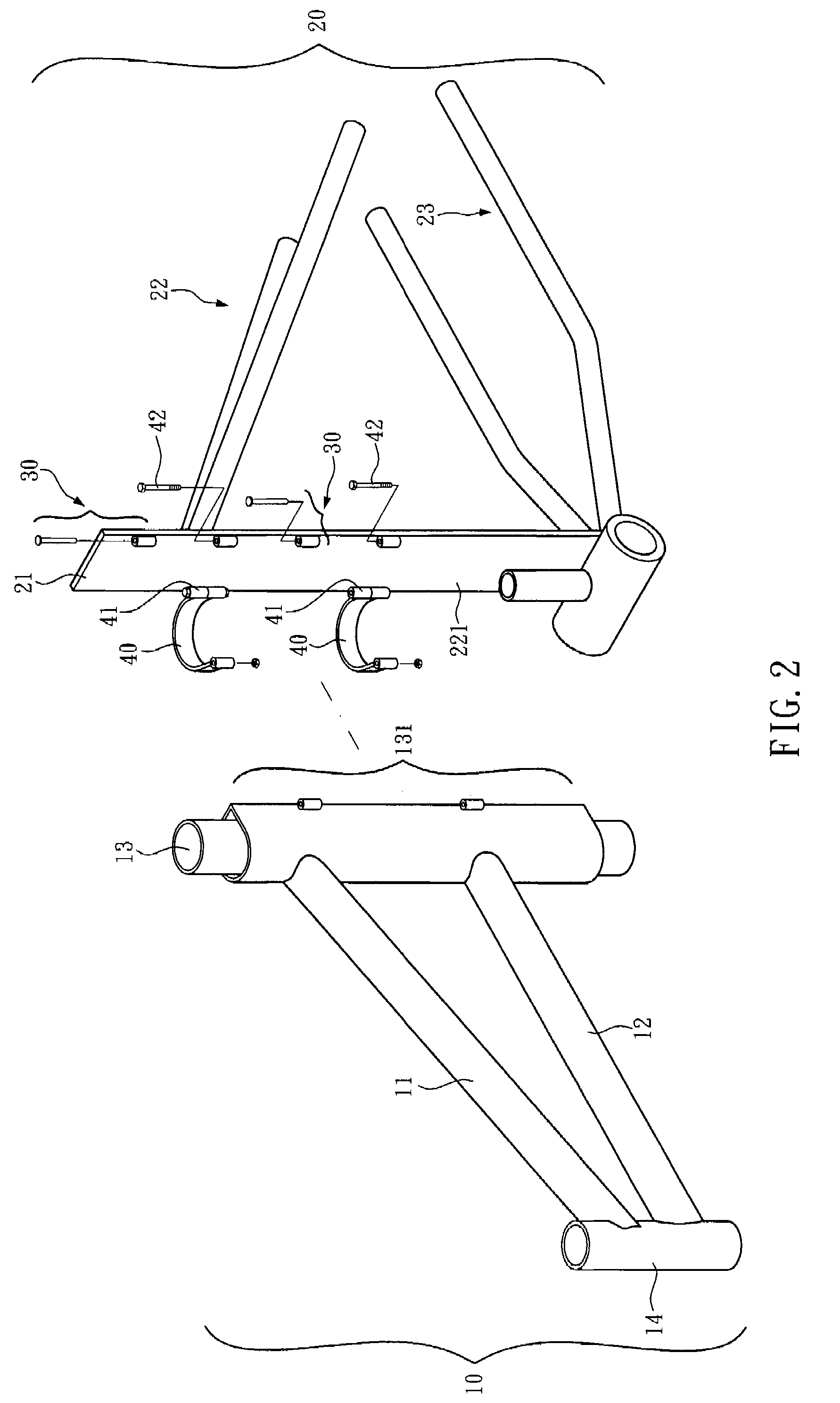
[0024]For clarifying the concept of the present invention, a preferred embodiment is herein provided for the purpose of illustration and it is to be stated firstly that the components of the depicted embodiment are not made to scale. As shown in FIGS. 2 and 3, a folding frame of a bicycle according to the present invention primarily comprises a front frame member 10 and a rear frame member 20. The front frame member 10 includes a top tube 11, a down tube 12, a seat tube 13 and a head tube 14. The top tube 11 and the down tube 12 are horizontally welded with the seat tube 13 and head tube 14, which are vertically positioned. The rear frame member 20 is primarily composed of a combining structure 21, a rear fork 22 and a pair of chain stays 23 welded together. Front ends of the rear fork 22 and the chain stays 23 are welded with the combining structure 21, respectively, while rear ends of the same components are connected with a rear fork tip (not shown).

[0025]At least one pivot struc...


PUM


Abstract

The disclosed folding mechanism comprises a rear frame member of a bicycle, which has a combining structure positioned at a front portion thereof, wherein the combining structure includes a first joining surface; a front frame member of the bicycle, which has a second joining surface positioned at a rear portion thereof for being joined with the first joining surface; at least one pivot structure, which is provided at an edge of the combining structure for connecting the front frame member, such that the front and rear frame members can relatively move on the pivot structure; and at least one binder, which is deposited at the combining structure of the rear frame member and a position on the front frame member adjacent to the combining structure for fixing the second joining surface of the front frame member and the first joining surface of the rear frame member at a combining position where the two joining surfaces contact mutually. By using the folding mechanism, a bicycle equipped with the same can be folded or expanded.

Description

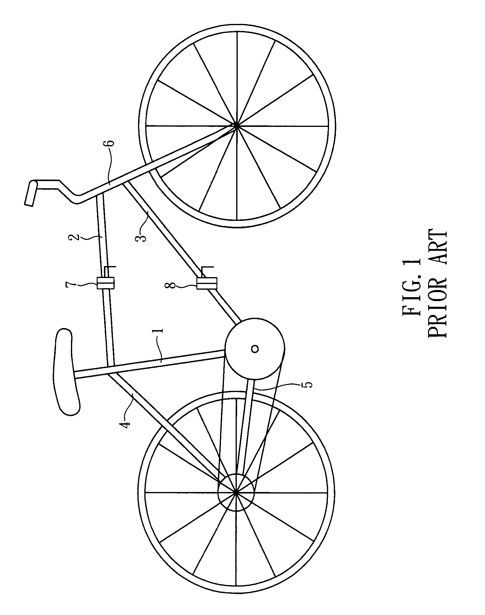
BACKGROUND OF THE INVENTION[0001]1. Technical Field[0002]The present invention relates to folding bicycles and, more particularly, to a folding bicycle frame with enhanced strength.[0003]2. Description of Related Art[0004]A conventional bicycle frame, as illustrated in FIG. 1, primarily comprises a seat tube 1 connected with a top tube 2, a down tube 3, a pair of seat stays 4 and a pair of chain stays 5 connected, respectively. Each of the top tube 2 and the down tube 3 has a front end thereof combined with a head tube 6, respectively. Each of the seat stays 4 and the chain stays 5 has a rear end thereof jointed at a rear fork tip. It can be observed that the seat tube 1, the top tube 2, and the down tube 3 collectively construct a triangular frame as a main force structure of the entire bicycle frame. The integrity of the force structure ensures the structural strength and resistance to compression, bend and deformation. However, a conventional folding bicycle frame typically has f...

Claims


Application Information

Patent Timeline
Patent Type & Authority Patents(United States)
IPC IPC(8): B62K3/14
CPCB62K15/006
Inventor HUANG, ALFREDCHIU, WEN-PINLAI, YUNG-CHENHUANG, YU-CHE
Owner CYCLING & HEALTH TECH IND R & D CENT
Learn More