
Anti-intrusion pedal system

a pedal system and anti-intrusion technology, applied in mechanical control devices, instruments, tractors, etc., can solve the problems of increasing mass and needing additional space, and achieve the effect of reducing the rearward movement of the pedal, ensuring layout flexibility, and reducing the increase in mass

Inactive Publication Date: 2010-03-02
MAZDA MOTOR CORP
View PDF13 Cites 2 Cited by
  • Summary
  • Abstract
  • Description
  • Claims
  • Application Information

AI Technical Summary

Benefits of technology

The present invention relates to an anti-intrusion bracket for preventing a pedal from being moved rearward in a vehicle collision. The invention aims to prevent the pedal from being moved rearward while still maintaining flexibility in the vehicle body and restraining the increase in mass. The anti-intrusion bracket is mounted on the accessory disposed to the lateral side of the steering shaft or the electric power steering unit, and it abuts on the pedal pushed rearward in a collision to prevent further movement. The invention provides a reliable solution for preventing pedal movement in a collision without adding extra space or weight to the vehicle body.

Problems solved by technology

Therefore, in order that the above anti-intrusion pedal system is applied to car body structures in which car body members do not exist in the vicinity of the pedal, the guide member must be disposed through an additional bracket or must be upsized, which arises problems of increasing the mass and needing an additional space.

Method used


Image

  • Anti-intrusion pedal system
  • Anti-intrusion pedal system
  • Anti-intrusion pedal system

Examples


Embodiment Construction

[0028]Embodiments of the present invention will be described below with reference to the drawings.

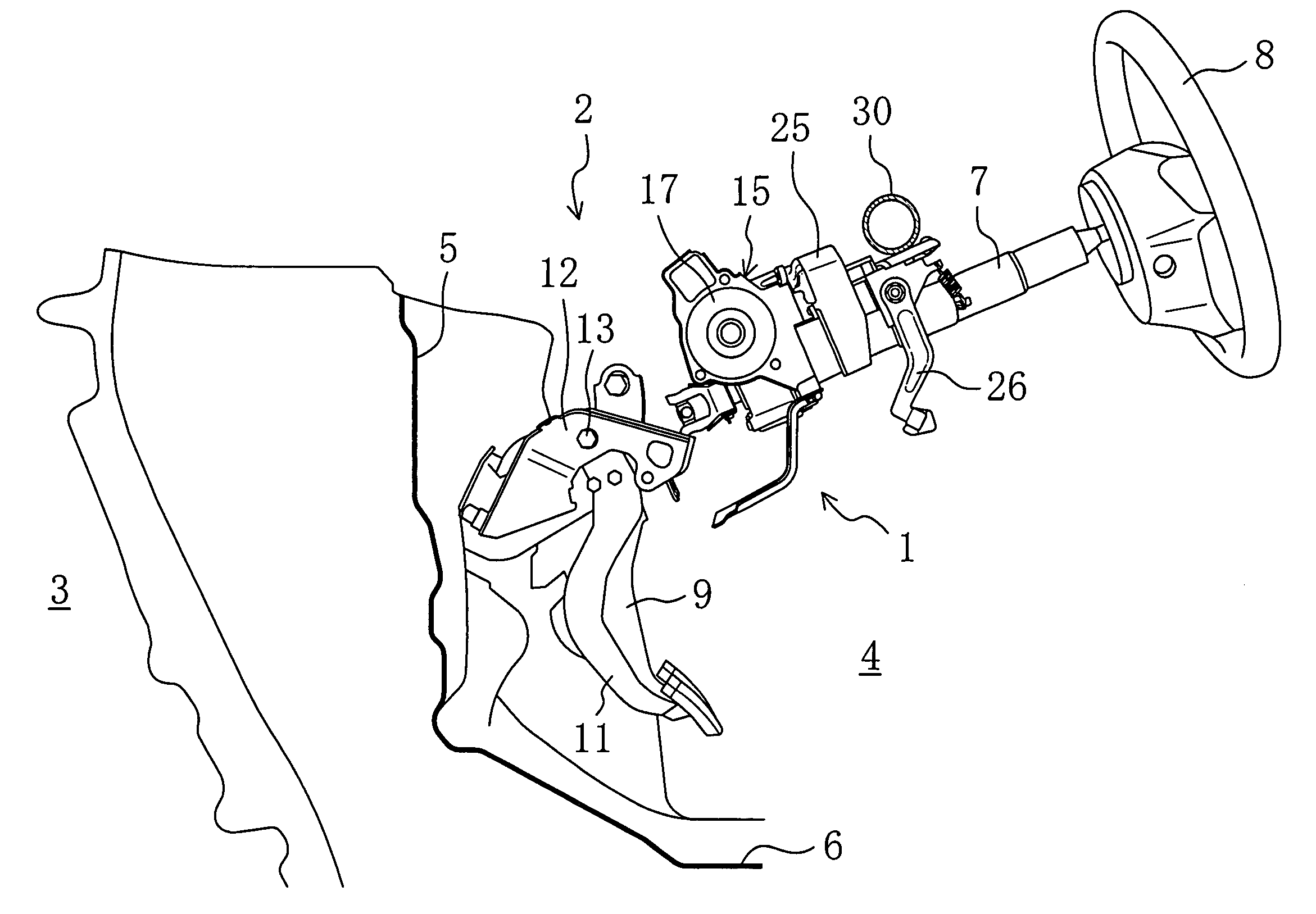
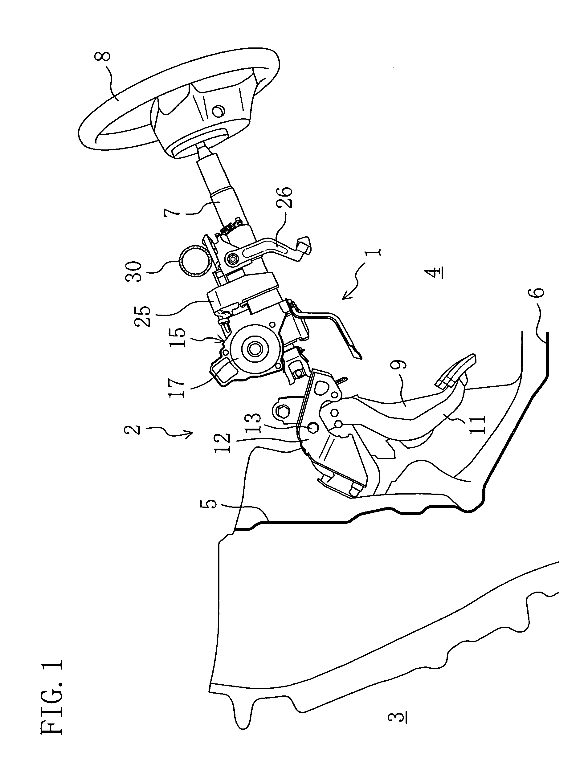
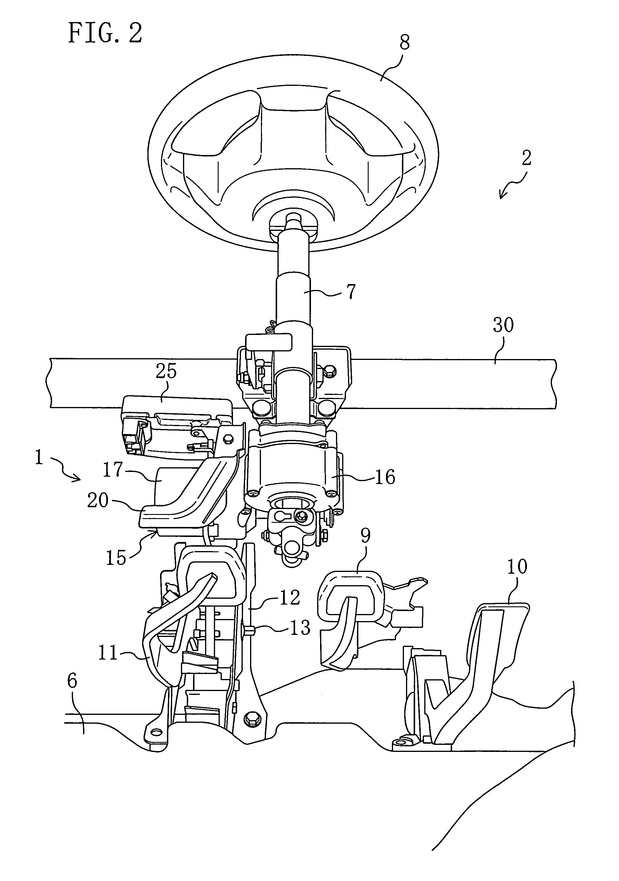
[0029]FIG. 1 shows a front part 2 of a driver's seat with an anti-intrusion pedal system 1 according to an embodiment of the present invention. FIG. 2 shows the driver's seat front part 2 as viewed from below and the rear. For simplicity, a dash panel 5 is not given in FIG. 2.

[0030]In the driver's seat front part 2, a steering shaft 7 extends at an angle rearward and upward from between a floor panel 6 and the dash panel 5 partitioning an engine room 3 and a cabin 4 (but, for simplicity, a lower part of the steering shaft 7 passing through the floor panel 6 is not given in the figures). The steering shaft 7 acts to transmit a steering force from the steering wheel 8 to road wheels (not shown) of the car. Further, the driver's seat front part 2 is provided with an instrument panel member 30 extending in the car width direction. The instrument panel member 30 is connected to an A frame (n...


PUM


Abstract

Road wheels of a vehicle are provided with a steering shaft for transmitting a steering force from a steering wheel. An electric power steering unit (accessory) is disposed to a lateral side of the steering shaft. A clutch pedal is disposed below the electric power steering unit and pivotally mounted to a dash panel. The electric power steering unit is provided with an anti-intrusion bracket extending to the vicinity of the rear of the clutch pedal so that the anti-intrusion bracket can abut on the clutch pedal pushed rearward in a collision.

Description

CROSS-REFERENCES TO RELATED APPLICATIONS[0001]This application claims priority under 35 USC 119 to Japanese Patent Application No. 2005-278431 filed on Sep. 26, 2005, the entire contents of which are incorporated herein by reference.BACKGROUND OF THE INVENTION[0002](a) Field of the Invention[0003]This invention relates to anti-intrusion pedal systems for preventing a pedal from being moved rearward in a vehicle collision.[0004](b) Description of the Related Art[0005]As disclosed, for example, in Japanese Patent Laid-Open Publication (Kokai) No. 2003-54390, there is conventionally known an anti-intrusion pedal system in which a parking brake pedal is fixed at its front part to a dash panel and is connected at its upper part through a connecting member to an instrument panel member located to the rear of the dash panel and extending in the car width direction and a guide member for abutting on the connecting member upon rearward movement of the dash panel due to a vehicle collision to...

Claims


Application Information

Patent Timeline
Patent Type & Authority Patents(United States)
IPC IPC(8): B60R21/05B60K23/02B60R21/02B60T7/06B62D5/00B62D25/08G05G1/32
CPCB60R21/09B60T7/065Y10T74/20528Y10T74/20888
Inventor SANAGI, SHUJITERADA, TAKESHI
Owner MAZDA MOTOR CORP
Learn More