Liquid application device and inkjet recording apparatus

a liquid application and inkjet recording technology, applied in printing, other printing apparatus, etc., can solve the problems of vaporization of application liquid, leakage of application liquid, and inability to obtain uniform coating film, etc., and achieve the effect of reducing non-uniform application of liquid

Inactive Publication Date: 2010-03-02
CANON KK
View PDF16 Cites 9 Cited by
  • Summary
  • Abstract
  • Description
  • Claims
  • Application Information

AI Technical Summary

Benefits of technology

[0013]An object of the present invention is to provide a liquid application device and an inkjet recording apparatus, which are capable of reducing nonuniform application of liquid to a medium.
[0015]In second aspect of the present invention, a liquid application device comprises: liquid application means including an application member for applying liquid to a medium, and a retention member for retaining the liquid in a liquid retention space formed in contact with the application member, wherein the liquid application means applies the liquid retained in the liquid retention space to the medium via the application member by rotating the application member; storage unit for storing the liquid; passage which cause the storage means and the retention member to communicate with each other; and circulating means for circulating the liquid in a channel including the storage unit, the passage, and the liquid retention space; wherein, the circulating means make a circulation speed of the current circulation operation faster, or a circulation period of the current circulation operation longer, as lapse of time after the previous circulation operation takes longer.
[0020]According to the present invention, a circulation operation is controlled on liquid in accordance with the lapse of time after the previous circulation operation. In so doing, the circulation operation is executable as being suitable for the degree of vaporization of the liquid, the degree varying depending upon the lapse of time. As a result, the thickening and / or the sticking of the liquid in the channel are reduced, and it becomes possible to reduce nonuniformity in the application derived from these thickening and / or sticking.

Problems solved by technology

As a result, when application media with a relatively small size are intermittently fed, and the application is performed to these media, the problem can occur that a uniform coating film cannot be obtained due to the irregularities of beads of coating material at the start or the end point of the application, for example.
For this reason, there arises the problem of vaporization of the application liquid.
In addition, there is a possibility that the problem can occur that, when the position of the apparatus changes, this results in the leakage of the application liquid.
Among others, with regard to the inkjet recording apparatuses, such as printers, with the leakage of the liquid due to the position change at the time of carrying taken into consideration, it is difficult to apply the application mechanism described in the above documents to downsized apparatuses.
As a result it is sometimes made difficult to perform favorable circulation to the extent that reliability of the application device can be maintained.
There is concern that this nonuniformity adversely affects the image to be printed eventually such as mottling.

Method used


Image

  • Liquid application device and inkjet recording apparatus
  • Liquid application device and inkjet recording apparatus
  • Liquid application device and inkjet recording apparatus

Examples


first embodiment

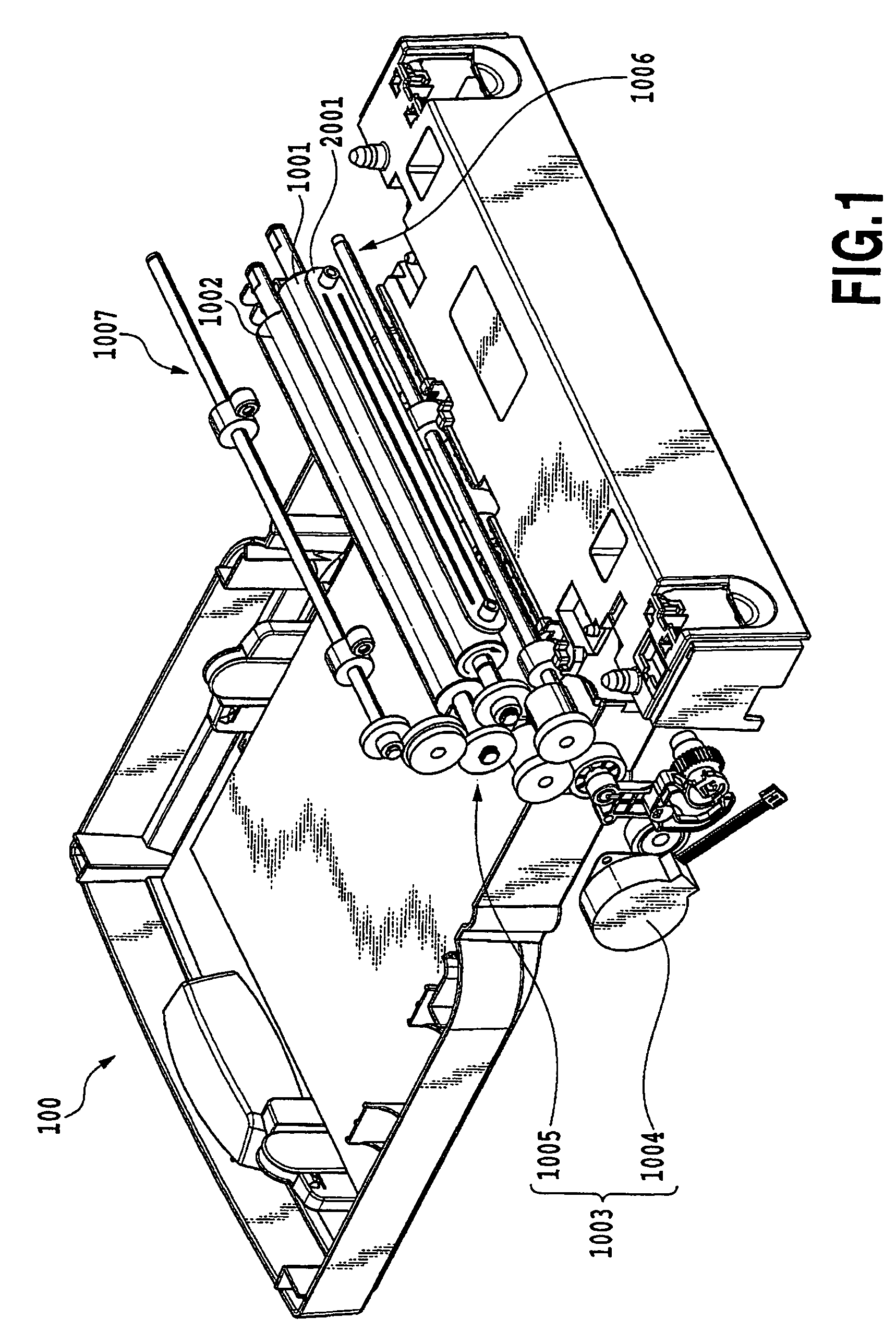
[0048]FIG. 1 is a perspective view showing an overall structure of the embodiment of a liquid application device 100 of the present invention. The liquid application device 100 shown here generally includes liquid application means for applying a predetermined application liquid to a medium (hereinafter also referred to as the application medium) which is an object to which the liquid is applied and liquid supply means for supplying the application liquid to the liquid application means.

[0049]The liquid application means includes a cylindrical application roller 1001, a cylindrical counter roller (a medium supporting member) 1002 placed so as to face the application roller 1001 and a roller drive mechanism 1003 driving the application roller 1001. The roller drive mechanism 1003 includes a roller drive motor 1004 and a power transmission mechanism 1005 including a gear train for transmitting the driving force of the roller drive motor 1004 to the application roller 1001.

[0050]The li...

second embodiment

[0115]In the first embodiment, the optimum preliminary circulation sequence is selected corresponding to the obtained lapse of time after the previous circulation operation. In addition to this, the optimum preliminary circulation sequence may be configured to be selected corresponding to a state of each of the portions at the start of the preliminary circulation after the lapse of time. In this embodiment, the preliminary circulation sequence is determined based not only on the lapse of time after the previous circulation operation, but also on whether or not there is the application liquid in the liquid retention space S at the start of the preliminary circulation.

[0116]FIG. 17, which is a flow chart showing a procedure relating to a preliminary circulation step according to the embodiment of the present invention, is a flow chart showing a procedure relating a preliminary circulation step corresponding to step S1 of FIG. 13.

[0117]In step S31, the CPU 4001 obtains information indi...


PUM


Abstract

A liquid application device and an inkjet recording apparatus are capable of reducing nonuniformity in application of liquid onto a recording medium, and thereby forming high-quality images on a steady basis. In the present invention, information indicating the lapse of time after the previous circulation operation is obtained. Subsequently, based on the obtained information indicating the lapse of time, a preliminary circulation sequence is determined. Finally, the preliminary circulation sequence is performed based on the determined preliminary circulation sequence.

Description

BACKGROUND OF THE INVENTION[0001]1. Field of the Invention[0002]The present invention relates to a liquid application device and an inkjet recording apparatus, and particularly to a liquid application device for applying liquid to a medium for a certain purpose which is, for example, to promote the coagulation of pigment when recording is carried out using an ink which contains the pigment as a coloring material. The present invention also relates particularly to an inkjet recording apparatus which includes a mechanism for applying liquid to a recording medium used in inkjet recording, for a purpose which is, for example, to promote the coagulation of pigment when recording is carried out using an ink containing the pigment as a coloring material.[0003]2. Description of the Related Art[0004]As modes of widely applying liquid or liquid material to a medium, spin coaters, roll coaters, bar coaters, and die coaters are known. These application modes are adopted on the assumption that t...

Claims


Application Information

Patent Timeline
Patent Type & Authority Patents(United States)
IPC IPC(8): B41J2/175
CPCB41J11/0015
Inventor OSHIO, NAOMIOTSUKA, NAOJIIWASAKI, OSAMUNAKAGAWA, YOSHINORIMASUYAMA, ATSUHIKO
Owner CANON KK
Why Eureka
Try Eureka