Dissipation module,flat heat column thereof and manufacturing method for flat heat column

a technology of heat dissipation module and heat dissipation module, which is applied in the direction of tubular elements, lighting and heating apparatus, and strengthening means, etc. it can solve the problems of low welding reliability, long welding path, and increase in heat energy while using electronic devices, so as to increase the circulating flow rate of working fluid, increase the reliability of welding, and effectively enhance the effect of heat dissipation efficiency

Inactive Publication Date: 2010-03-04
DELTA ELECTRONICS INC
View PDF14 Cites 11 Cited by
  • Summary
  • Abstract
  • Description
  • Claims
  • Application Information

AI Technical Summary

Benefits of technology

[0008]In view of the foregoing, the present invention is to provide a flat heat column, which has high reliability, low cost and high thermal conductive efficiency, and a manufacturing method thereof.
[0011]To achieve the above, the present invention is to provide a heat dissipation module according to a method for manufacturing a flat heat column of the present invention, rather than being conventionally formed by an upper plate and a lower plate. Thus, the reliability can be increased by reducing the number of welding paths, a guiding device can be disposed at any position in the flat hollow column, and a continuous wick structure can be formed by a wick structure on a condensation end and a wick structure on a vaporization end. This helps prevent a capillary force for a working fluid from being interrupted, in which the working fluid flows from the condensation end to the vaporization end through the guiding device, so as to increase the circulating flow rate of the working fluid, hence effectively enhance the heat dissipation efficiency. Compared to the conventional flat heat plate having a discontinuous wick structure, the structure and the method for manufacturing the flat heat column according to the present invention can provide a more preferable wick structure that makes the working fluid circulate quickly and enhances thermal conductivity.
[0012]In addition, a method is provided for manufacturing the flat heat column of the present invention allows an outer surface of the flat heat column formed by stamping instead of the flat heat plate that is formed in a complicated way such as welding or at high cost, the length of the flat heat column can be adjusted according to the requirements of different users, and the mold is cheap and can be shared. Thus, the manufacturing process of the present invention can be simplified. In general, the method for manufacturing the flat heat column of the present invention has the advantages of low cost and that the flat heat column can be easily changed to different shapes.

Problems solved by technology

Accompanying the development of the technology, the number of transistors on a same unit area of the electronic device has been increasing, and this leads to an increase in heat energy while using the electronic device.
Since the flat heat plate is conventionally formed by welding an upper plate and a lower plate together, not only that the welding path is long and the welding reliability is low, but also that the wick structures on the upper and lower plates are not able to be continuously connected but merely connected by contacting.
Additionally, in the conventional method of welding the upper and the lower plates, since a lot of elements and a high level of mold / fixture technique are needed, the cost of the conventional method is relatively higher.
Furthermore, different molds and fixtures have to be used for the flat heat plates with different lengths, so the cost of equipment is largely increased.

Method used


Image

  • Dissipation module,flat heat column thereof and manufacturing method for flat heat column
  • Dissipation module,flat heat column thereof and manufacturing method for flat heat column
  • Dissipation module,flat heat column thereof and manufacturing method for flat heat column

Examples


Embodiment Construction

[0023]The present invention will be apparent from the following detailed description, which proceeds with reference to the accompanying drawings, wherein the same references relate to the same elements.

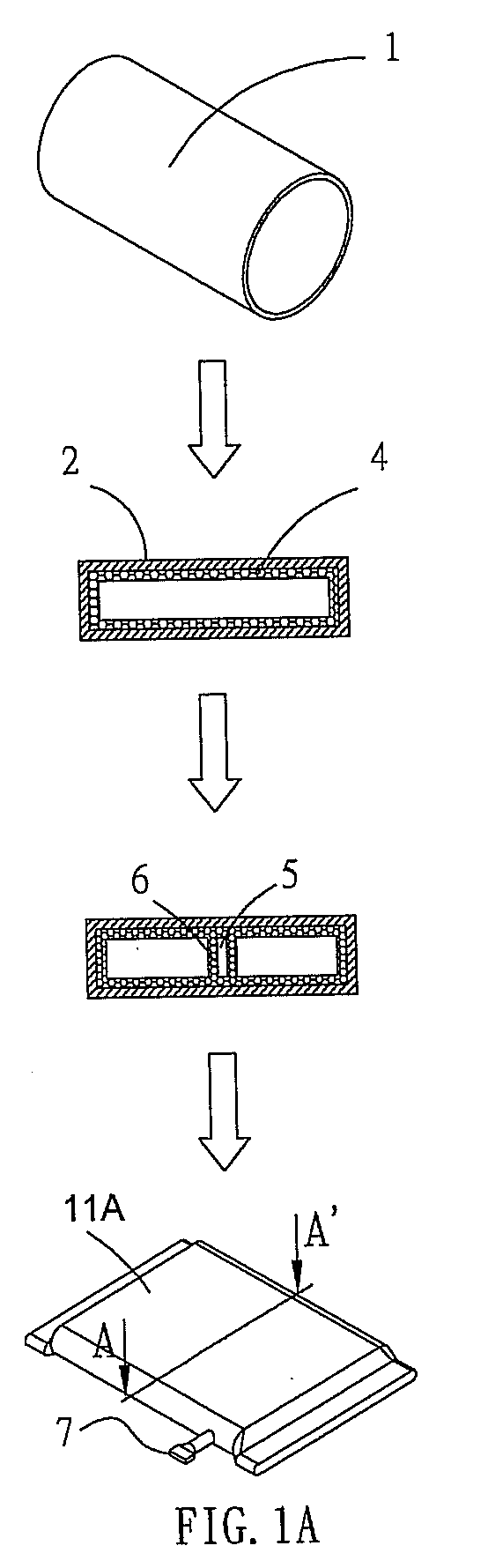
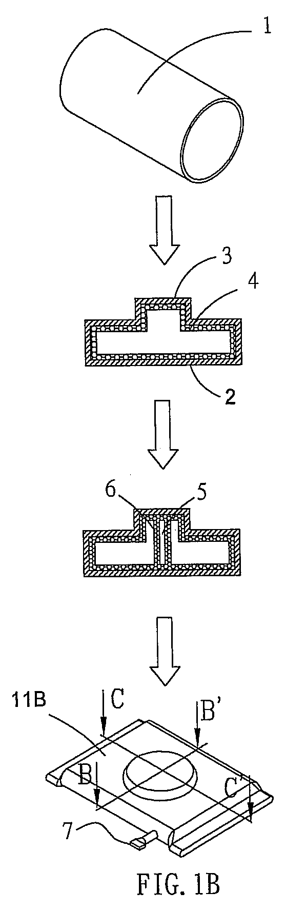
[0024]FIGS. 1A and 1B are schematic illustrations of manufacturing processes of two flat heat columns according to the present invention. A method for manufacturing a flat heat column is illustrated as follows. With reference to FIGS. 1A and 1B, firstly, a flat hollow tube 2 that is provided is, for example, a circular tube 1 formed by stamping, and its cross-sectional shape is rectangular. The cross-sectional shape of the circular tube 1 can also be polygon, oblong, or long arc. The material of the tube is, for example, aluminum (Al), copper (Cu), titanium (Ti), molybdenum (Mo), or other metal with high thermal conductivity. It is to be noted that the flat hollow tube 2 can be not only formed by applying a stamping process to a circular tube 1 but also directly formed by stamping.

[00...


PUM

PropertyMeasurementUnit
thermal conductivityaaaaaaaaaa
thermal conductiveaaaaaaaaaa
heat energyaaaaaaaaaa

Abstract

A manufacturing method for a flat heat column includes the steps of: providing a flat hollow tube, of which a first wick structure is disposed on the inner surface; providing at least one guiding device disposed within the flat heat tube for supporting the flat heat tube, wherein a second wick structure is disposed on the surface of the guiding device; connecting the first wick structure and the second wick structure for forming a continuous wick structure; and filling a working fluid and sealing both two ends of the flat hollow tube so as to form the flat heat column. A heat dissipation module and its flat heat column are also disclosed for applying to a heat element. The flat heat column can provide flowing path with optimum thermal conductive efficiency for the fluid therein.

Description

CROSS REFERENCE TO RELATED APPLICATIONS[0001]This Non-provisional application claims priority under 35 U.S.C. §119(a) on Patent Application No(s). 097132974 filed in Taiwan, Republic of China on Aug. 28, 2008, the entire contents of which are hereby incorporated by reference.BACKGROUND OF THE INVENTION[0002]1. Field of Invention[0003]The present invention relates to a heat dissipation module and in particular to a heat dissipation module having a guiding device disposed in a hollow tube and the guiding device has a wick structure.[0004]2. Related Art[0005]Accompanying the development of the technology, the number of transistors on a same unit area of the electronic device has been increasing, and this leads to an increase in heat energy while using the electronic device. The heat pipe is a simple but very effective heat dissipation device, and it has been widely applied on various electronic heat dissipation products. The heat pipe is used to transfer the energy by the latent heat p...

Claims


Application Information

Patent Timeline
Patent Type & Authority Applications(United States)
IPC IPC(8): F28D15/00B21D53/02
CPCF28D15/04Y10T29/49353F28F2225/04F28F1/022F28D15/0233F28D15/046
Inventor LIN, CHI-FENGCHUANG, MING-TE
Owner DELTA ELECTRONICS INC
Why Eureka
Try Eureka