Sheet piling wall having facade

Inactive Publication Date: 2010-03-02
BURKETT DARRYL SCOTT
View PDF10 Cites 2 Cited by
  • Summary
  • Abstract
  • Description
  • Claims
  • Application Information

AI Technical Summary

Benefits of technology

[0007]The configuration of the present invention seals effectively against water infiltration and freezing between the facade and the sheet piling which over time can cause cracking and separation of portions of the facade from the sheet piling.
[0008]According to another aspect of the invention, an over cap can be supported above the

Problems solved by technology

Walls for retaining water formed of sheet piling with a rock facade can suffer the drawback that water can infiltrate behind the rock facade and freeze d

Method used


Image

  • Sheet piling wall having facade
  • Sheet piling wall having facade
  • Sheet piling wall having facade

Examples


Embodiment Construction

[0018]While this invention is susceptible of embodiment in many different forms, there are shown in the drawings, and will be described herein in detail, specific embodiments thereof with the understanding that the present disclosure is to be considered as an exemplification of the principles of the invention and is not intended to limit the invention to the specific embodiments illustrated.

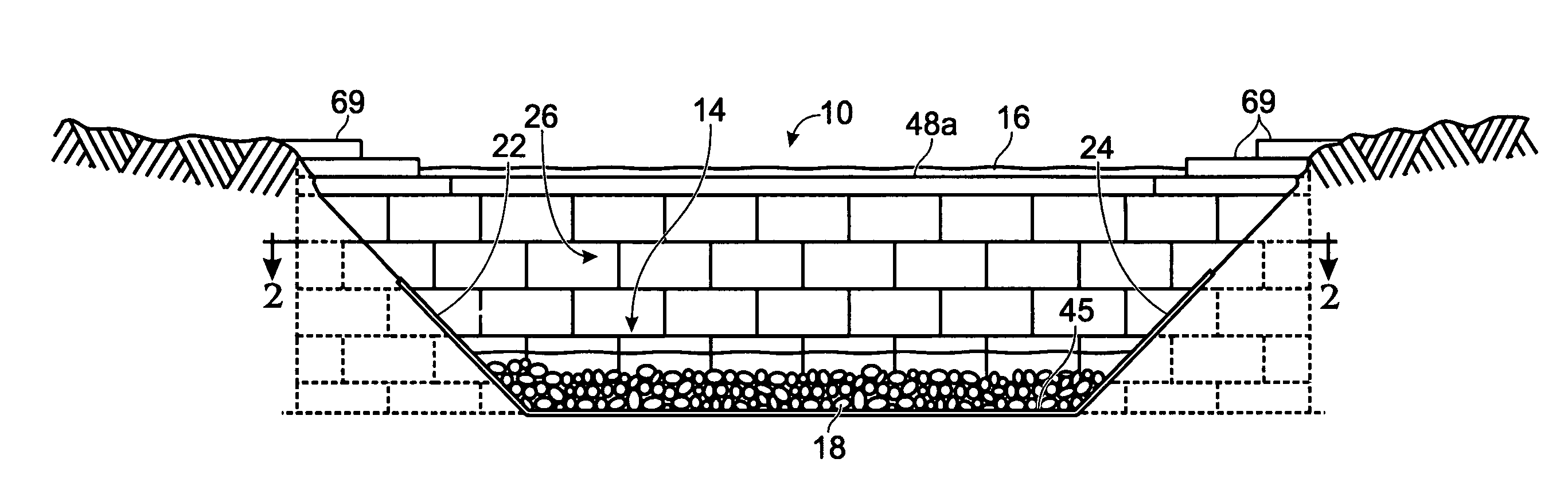
[0019]FIG. 1 illustrates a wall 10 of the invention in the form of a dam or waterfall, traversing a creek 14. A level of water 16 spills over the wall 10 onto a rock bed 18 arranged in front of the wall 10. The wall 10 is set into the left bank 22 and the right bank 24 of the creek 14. The wall 10 includes a rock or boulder facade 26.

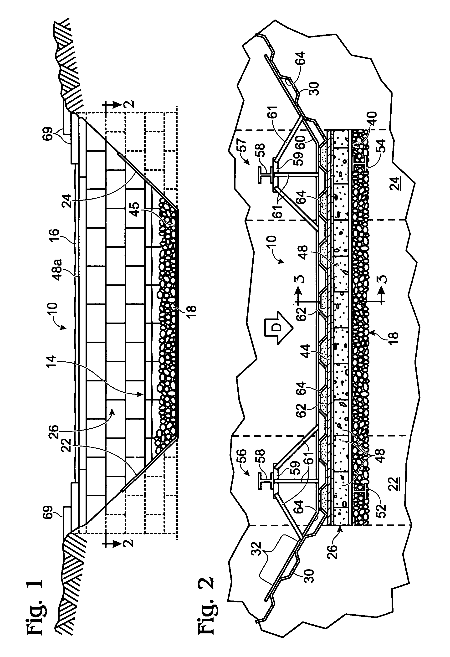
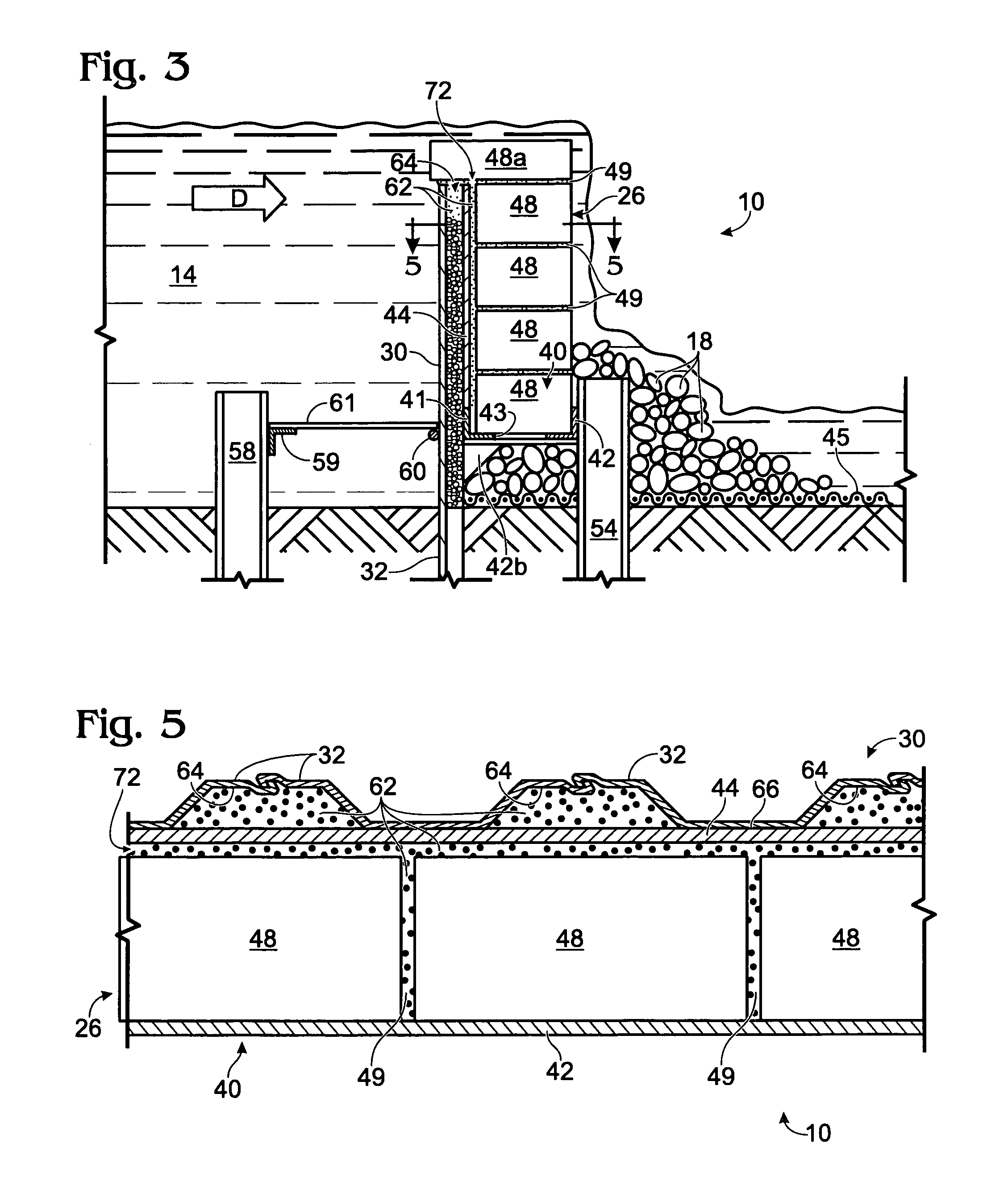
[0020]FIGS. 2-5 illustrate the construction of the wall 10 in more detail. The water flow in the creek is in the direction “D”. The wall 10 includes a length of steel sheet piling 30. The sheet piling 30 is typically driven into the ground to refusal, typically about...


PUM


Abstract

A wall for retaining water includes a backing support, formed by vertically arranged sheet piling, a base attached to the sheet piling, and a rock or boulder facade supported on the base. The sheet piling is formed of undulating, interlocking steel sheets. A backing plate is welded to the sheet piling. A high quality plaster is applied between the facade and the backing plate and between the backing plate and the sheet piling. Preferably, the plaster is a pool plaster type, typically used to seal cracks and form an exposed surface in in-ground swimming pools.

Description

RELATED APPLICATIONS[0001]This application claims the benefit of provisional application U.S. Ser. No. 60 / 642,667, filed Jan. 10, 2005.TECHNICAL FIELD OF THE INVENTION[0002]The present invention relates to walls constructed by sheet piling. Particularly, the present invention relates to a wall formed by a continuous steel sheet wherein the steel wall supports a boulder or stone facade, wherein the wall is particularly adapted to function as a dam, revetment, spillway or bank support.BACKGROUND OF THE INVENTION[0003]Walls formed of steel sheet piling that support a facade are known. Such walls are described for example in U.S. Pat. No. 635,165, or French Patent FR 2732375.[0004]Walls for retaining water formed of sheet piling with a rock facade can suffer the drawback that water can infiltrate behind the rock facade and freeze during cold temperatures. The freezing water expands away form the sheet piling and pushes the facade away from the sheet piling. After repeated freezing and t...

Claims


Application Information

Patent Timeline
IPC IPC(8): E02D5/02
CPCE02D5/02
Inventor BURKETT, DARRYL SCOTT
Owner BURKETT DARRYL SCOTT
Why Eureka
Try Eureka