System and method for pointing a laser beam

a laser beam and laser beam technology, applied in the direction of photometry using electric radiation detectors, optical radiation measurement, instruments, etc., can solve the problems of the least reliable component of the conventional laser beam pointer system, the pointer/tracker assembly, etc., and achieve the effect of eliminating the costly fine-track infrared camera and low cos

Inactive Publication Date: 2010-03-02
LOCKHEED MARTIN ACULIGHT CORP
View PDF21 Cites 37 Cited by
  • Summary
  • Abstract
  • Description
  • Claims
  • Application Information

AI Technical Summary

Benefits of technology

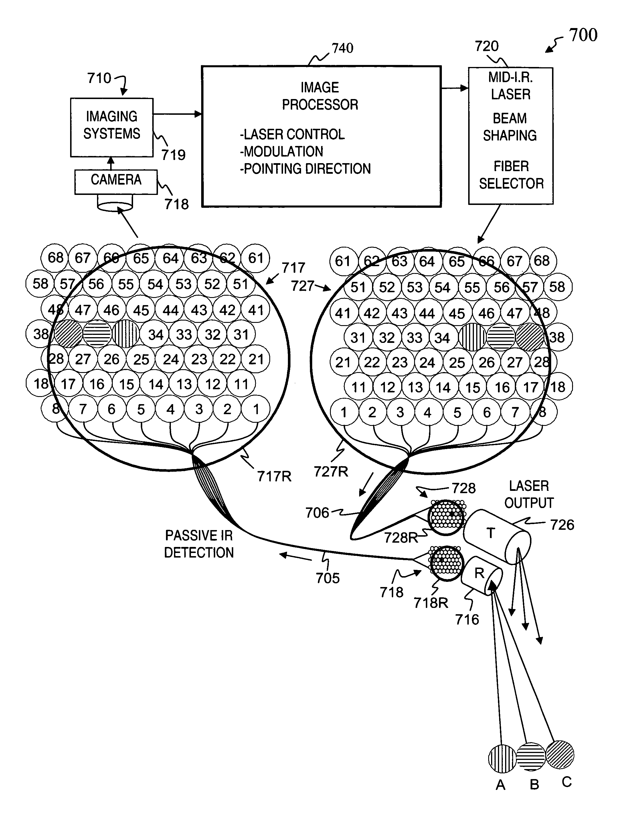
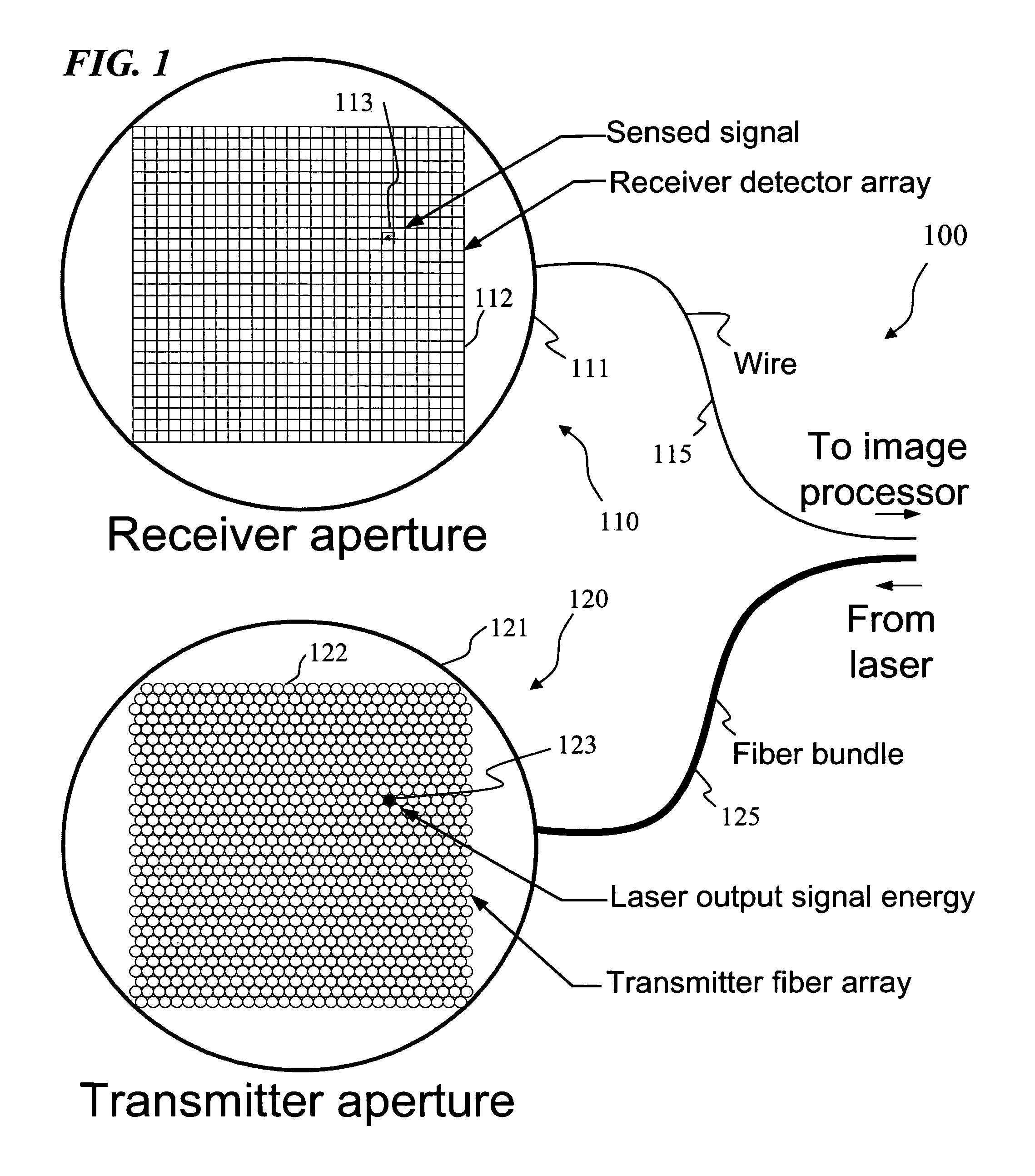
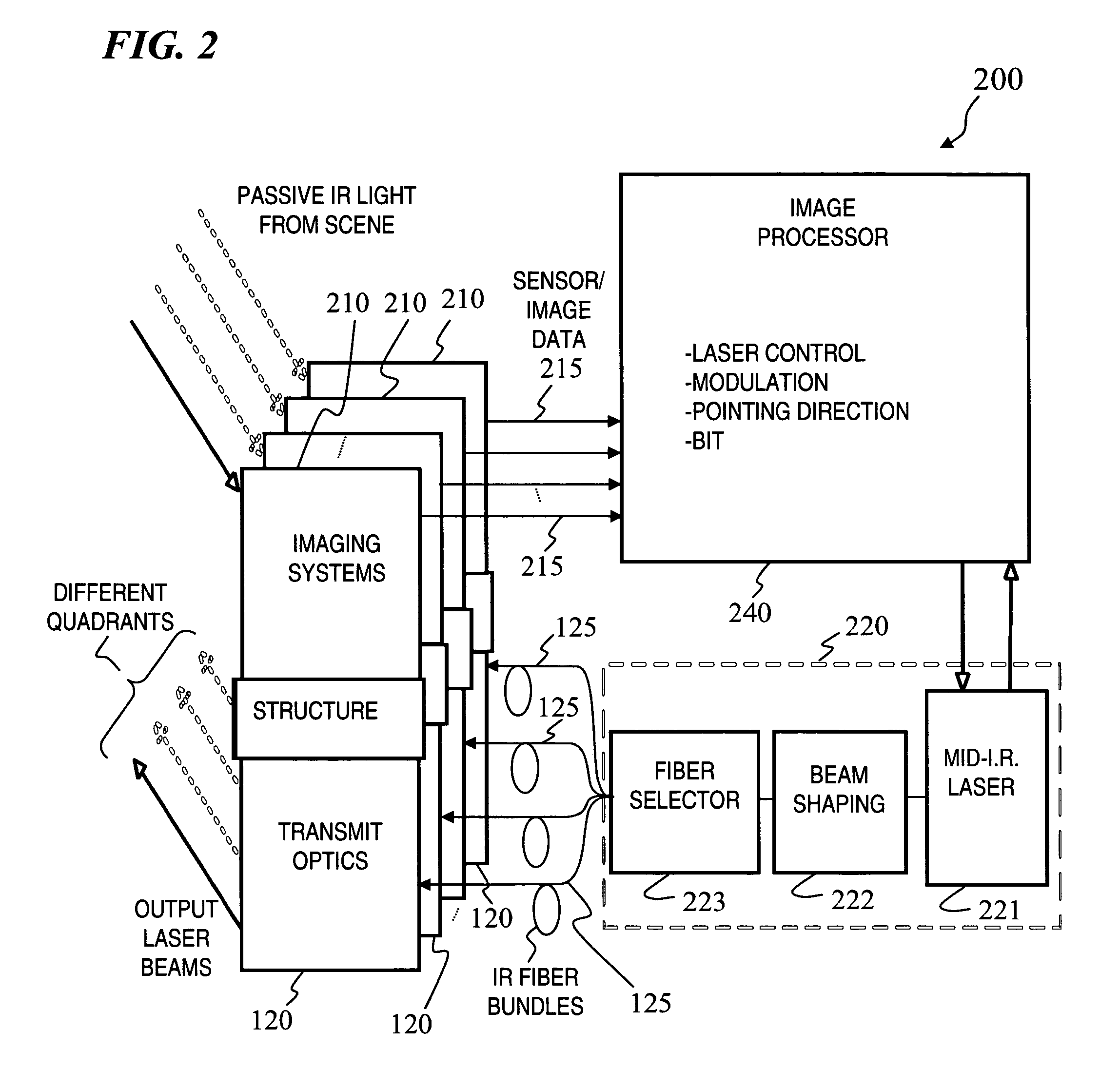
[0008]In some embodiments, the present invention provides a low-cost laser-pointer system that uses a distributed-aperture beam-steering system, eliminating the mechanical two- or three-axis gimbaled pointer. The pointer / tracker assembly is also the least reliable component in conventional laser-pointer systems. Further, the low-cost method and apparatus of the present invention use the existing or other conventional sensors for tracking what the laser beam should point at, eliminating the costly fine-track infrared camera.

Problems solved by technology

The pointer / tracker assembly is also the least reliable component in conventional laser-pointer systems.

Method used


Image

  • System and method for pointing a laser beam
  • System and method for pointing a laser beam
  • System and method for pointing a laser beam

Examples


Embodiment Construction

[0028]Although the following detailed description contains many specifics for the purpose of illustration, a person of ordinary skill in the art will appreciate that many variations and alterations to the following details are within the scope of the invention. Accordingly, the following preferred embodiments of the invention are set forth without any loss of generality to, and without imposing limitations upon the claimed invention.

[0029]In the following detailed description of the preferred embodiments, reference is made to the accompanying drawings that form a part hereof, and in which are shown by way of illustration specific embodiments in which the invention may be practiced. It is understood that other embodiments may be utilized and structural changes may be made without departing from the scope of the present invention.

[0030]The leading digit(s) of reference numbers appearing in the Figures generally corresponds to the Figure number in which that component is first introduc...


PUM


Abstract

Apparatus and method for directing a laser beam at an object. Some embodiments include generating direction-control information, based on the direction-control information, directing laser energy into a first fiber at a first end of a first fiber bundle during a first time period, forming an output beam of the laser energy from the second end of the first fiber bundle, and steering the output beam of the laser energy from the first fiber in a first selected direction of a plurality of directions during the first time period, and optionally modulating an intensity of the laser energy according to a predetermined pattern. The direction-control information is based on sensing electromagnetic radiation from a scene. Some embodiments use a remote camera wire-connected to the image processor to obtain scene information, while other embodiments use a second fiber bundle to convey image information from an external remote lens to a local camera.

Description

RELATED APPLICATIONS[0001]This invention claims benefit of U.S. Provisional Patent Application 60 / 740,968 filed on Nov. 29, 2005, which is hereby incorporated by reference in its entirety.STATEMENT OF GOVERNMENT INTEREST[0002]This invention was made with Government support under contract number DAAB0701-D-G001 from the U.S. Army. The government has certain rights in this inventionFIELD OF THE INVENTION[0003]The present invention relates to laser-beam pointer devices, and more particularly to apparatus and method for quickly determining a direction to which to point the laser beam and for directing the laser beam in the determined direction.BACKGROUND OF THE INVENTION[0004]Laser beams can be pointed using a number of methods and mechanisms, some which allow aligning the laser beam with a sensor-determined direction. Among these are methods using turrets and / or one or more gimbaled mirrors, for example U.S. Pat. No. 6,020,955 “System for pseudo on-gimbal, automatic line-of-sight align...

Claims


Application Information

Patent Timeline
Patent Type & Authority Patents(United States)
IPC IPC(8): G01J5/04
CPCF41G7/224F41H11/02F41H13/005G01J1/04G01J1/0425G01J1/4228G01S7/495G06F3/0304G06F3/0346G06F3/0386
Inventor TIDWELL, STEVEN C.
Owner LOCKHEED MARTIN ACULIGHT CORP
Why Eureka
Try Eureka