Dental Vacuum

a vacuum system and dental technology, applied in the field of dental vacuum systems, can solve the problems of short service life, poor flow, and noisy devices

Active Publication Date: 2012-11-15
FOXHAMMER
View PDF10 Cites 4 Cited by
  • Summary
  • Abstract
  • Description
  • Claims
  • Application Information

AI Technical Summary

Benefits of technology

[0010]The system according to embodiments of the invention involves a return to placing the entire system in the treatment room. Recent technology

Problems solved by technology

These devices were noisy, produced poor flow and were subject to short service lives.
In central dental vacuum systems, the equipment is out-of-sight, sometimes out of hearing range, and often out-of-mind.
However, as water quality and availability, as well as increasing w

Method used


Image

  • Dental Vacuum
  • Dental Vacuum
  • Dental Vacuum

Examples


Embodiment Construction

[0022]Unlike the prior central dental vacuum systems, the system of the preferred embodiments is a self-contained system that is constructed for in-treatment room use. A dental practice would thus use the dental system of the described embodiments in each treatment room of its facility.

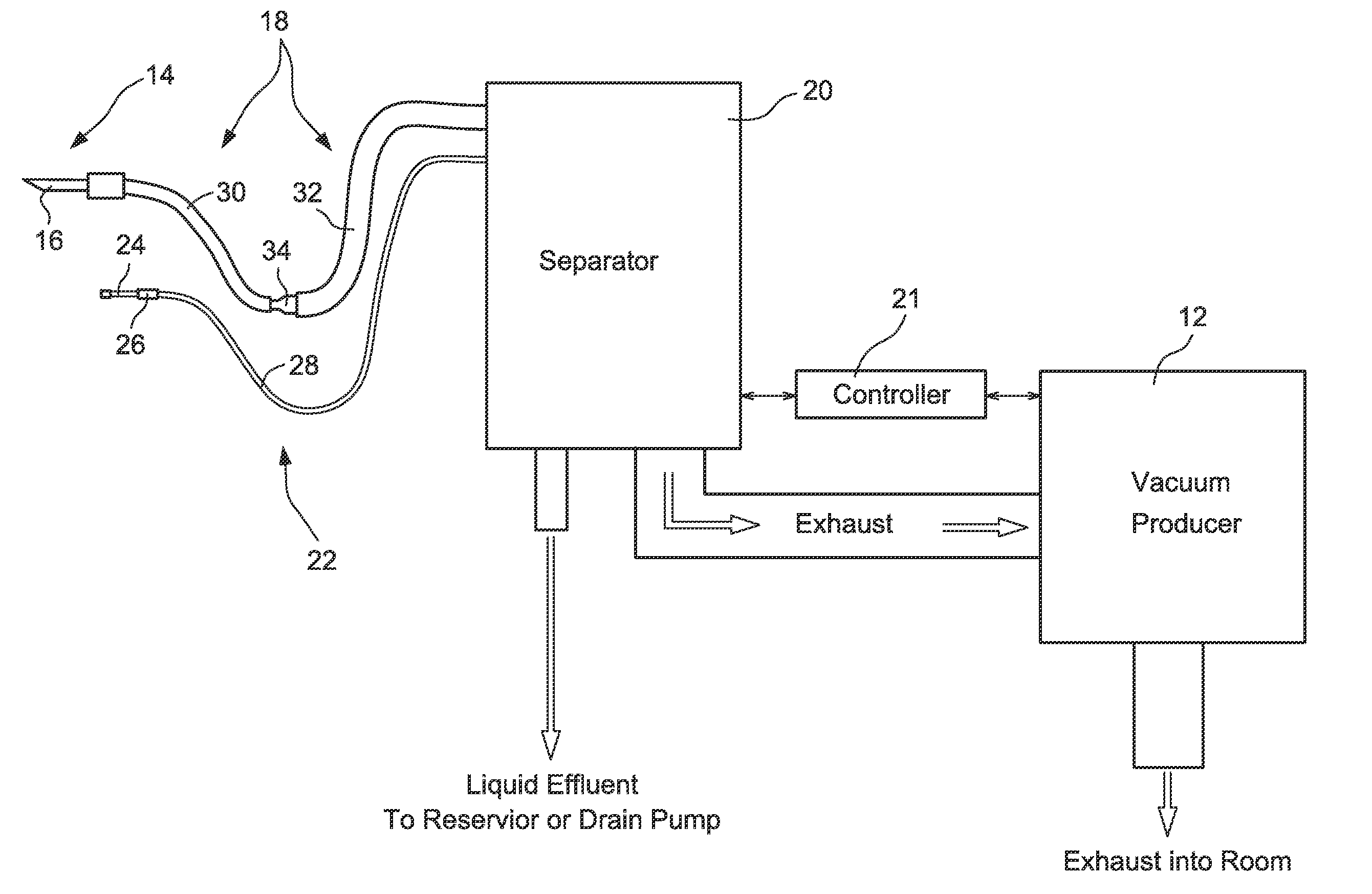
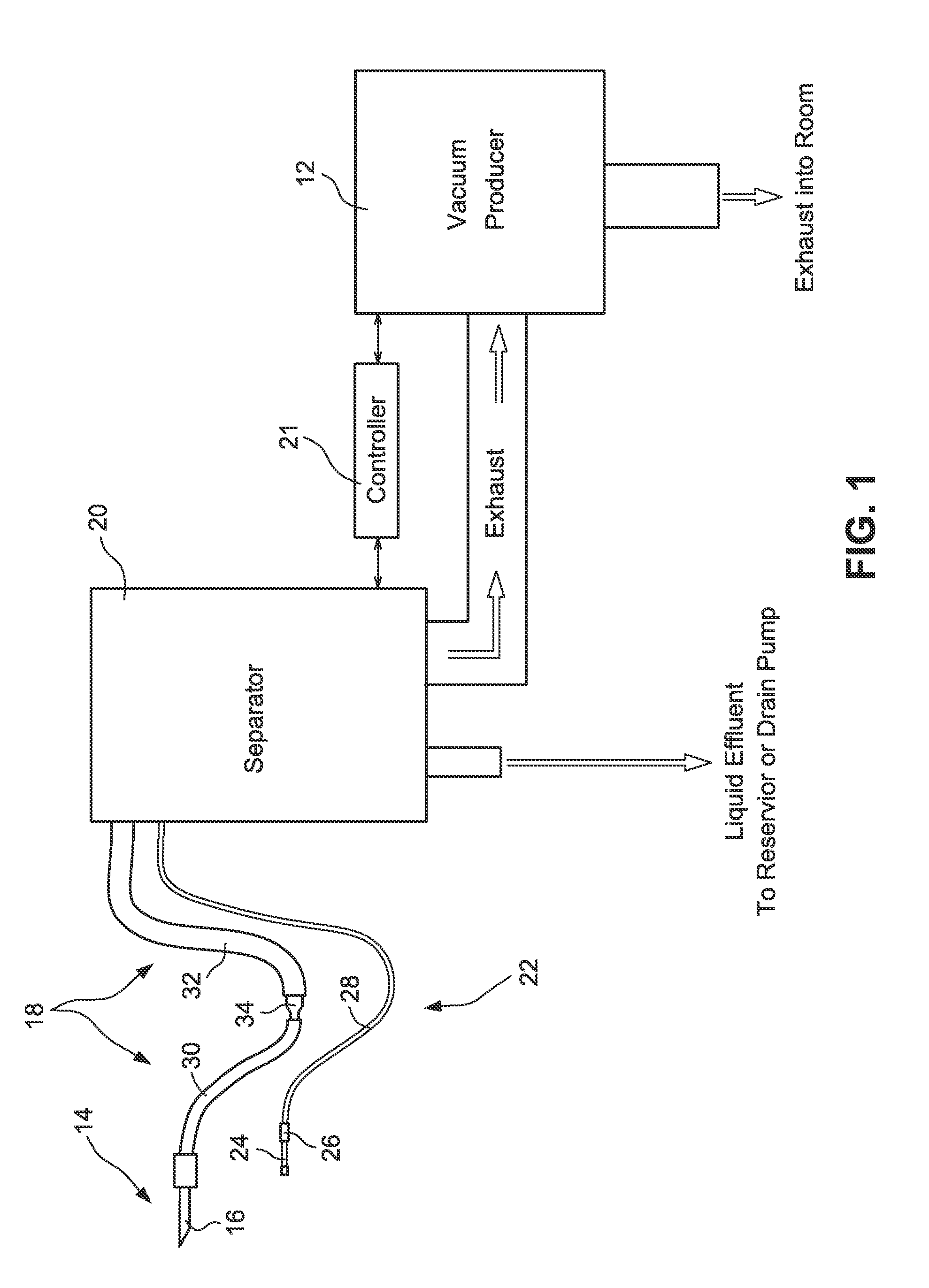
[0023]FIG. 1 is a schematic diagram of the dental vacuum system. A vacuum producer 12 generates a negative pressure (vacuum pressure) through the system. An operator tool 14 includes an evacuator tip (HVE tip) 16, and a hose assembly 18 connects the operator tool 14 to a separator 20. The separator 20 receives material from the operator tool 14 via the hose assembly 18 and separates the material into wet phase material and dry phase material. A controller 21 is cooperable with the vacuum producer 12 and the separator 20 to control operation of the system components. The system also includes a saliva ejector assembly 22 including a saliva ejector tip 24, a saliva ejector holder 26 and a saliva ejector ...


PUM


Abstract

An in-treatment room dental vacuum system includes a vacuum producer and an operator tool including an evacuator tip. A separator is coupled with the vacuum producer and is disposed between the vacuum producer and the operator tool. A hose assembly connects the operator tool and the separator. In use, the separator receives material from the operator tool via the hose assembly and separates the material into wet phase material and dry phase material.

Description

CROSS-REFERENCES TO RELATED APPLICATIONS[0001]This application claims the benefit of U.S.. Provisional Patent Application Ser. No. 61 / 485,182, filed May 12, 2011, the entire content of which is herein incorporated by reference.STATEMENT REGARDING FEDERALLY SPONSORED RESEARCH OR DEVELOPMENT[0002](NOT APPLICABLE)BACKGROUND OF THE INVENTION[0003]The invention relates to a dental vacuum system and, more particularly, to an in-treatment room dental vacuum system that provides for efficient operation with low power requirements, low maintenance and easily manageable, safe discharge.[0004]Many dental procedures require removing unwanted materials from the operating field. Removal actions are needed to improve visibility and to protect the patient from aspirating or swallowing dental materials or biological residue. Dental vacuum systems were created to meet this need.[0005]Initially the “dental vacuum system” consisted of a simple aspirating bulb. Later, water venturi systems were used. By...

Claims


Application Information

Patent Timeline
IPC IPC(8): A61C17/06A61C17/08
CPCA61C19/007
Inventor MEYER, ROBERT A.
Owner FOXHAMMER
Why Eureka
Try Eureka