Moving picture recording and sending device having zoom processing capability

Inactive Publication Date: 2010-03-02
HITACHI LTD
View PDF6 Cites 16 Cited by
  • Summary
  • Abstract
  • Description
  • Claims
  • Application Information

AI Technical Summary

Benefits of technology

[0005]To solve the above-described problems and achieve the above-stated object, the present invention is characterized by the provision of video signal switching means for mixing video signals of plural channels in time division; first video signal compressing means for compressing mixed video signals received from the video signal switching means; means for recording the video signal compressed by the first video signal compressing means onto a recording medium; second video sig

Problems solved by technology

However, it is necessary, when transmitting the video signal to a monitoring device at a remote location, to reduce the resolution and the time resolution in accordance with the limit of transmission capacity of the communication network.

Method used


Image

  • Moving picture recording and sending device having zoom processing capability
  • Moving picture recording and sending device having zoom processing capability
  • Moving picture recording and sending device having zoom processing capability

Examples


second embodiment

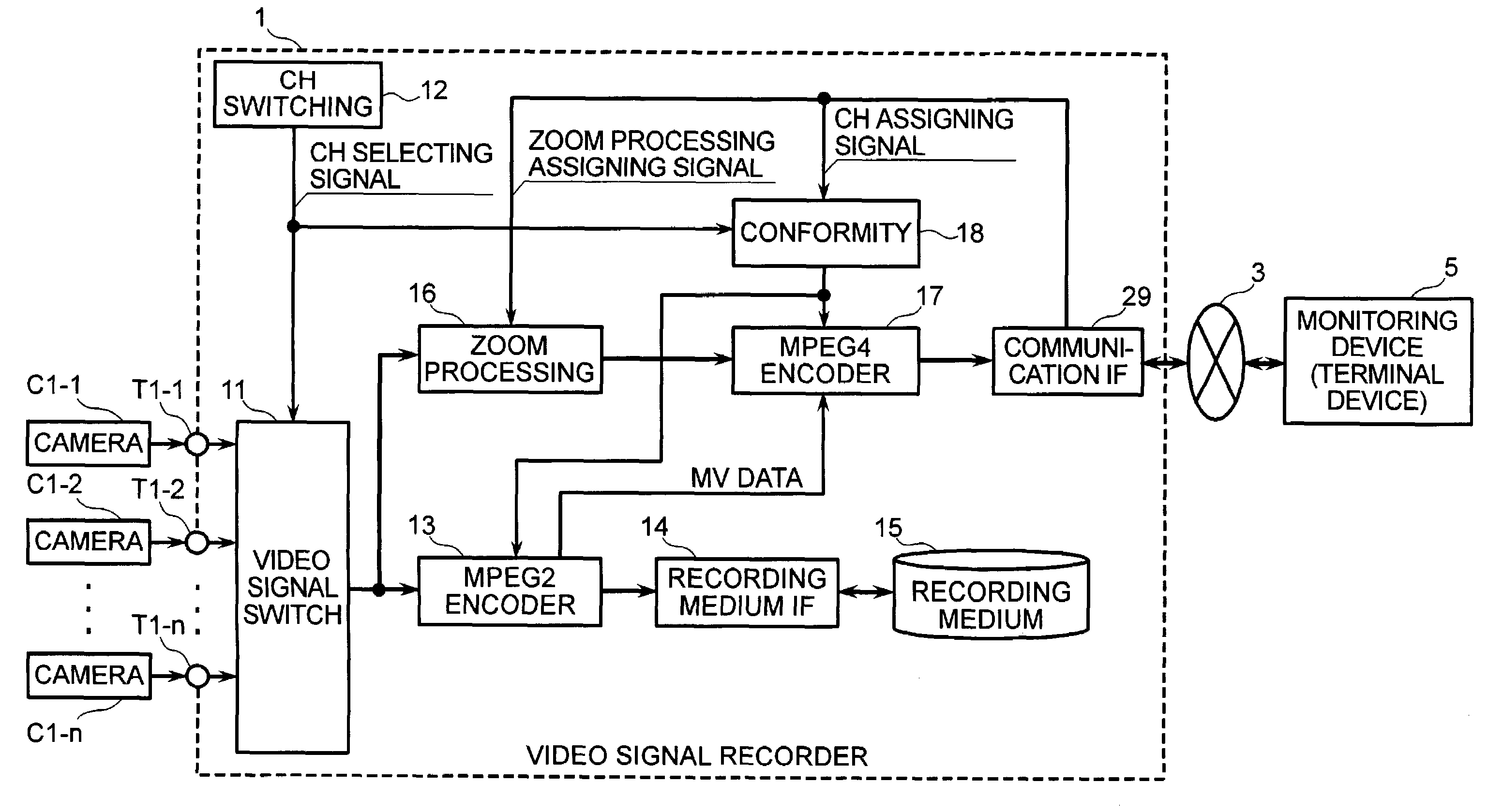
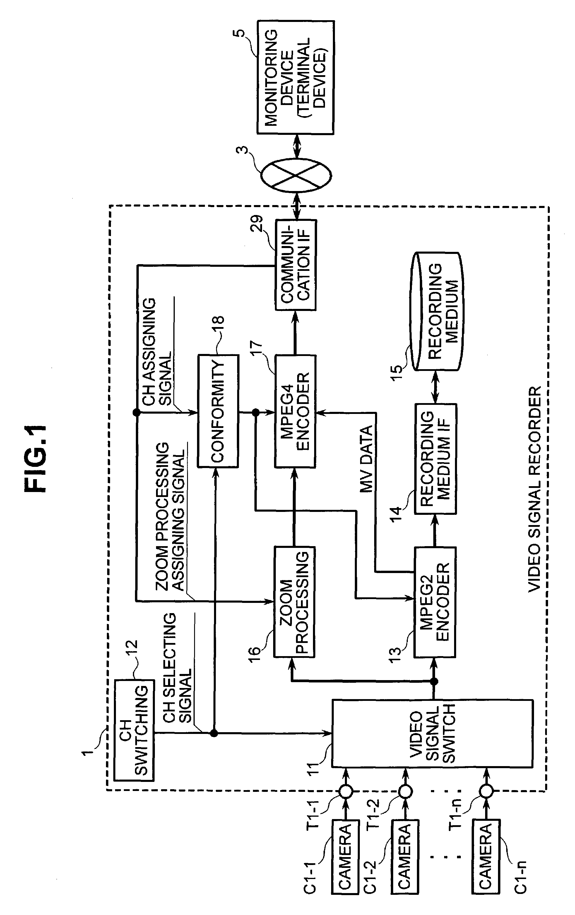
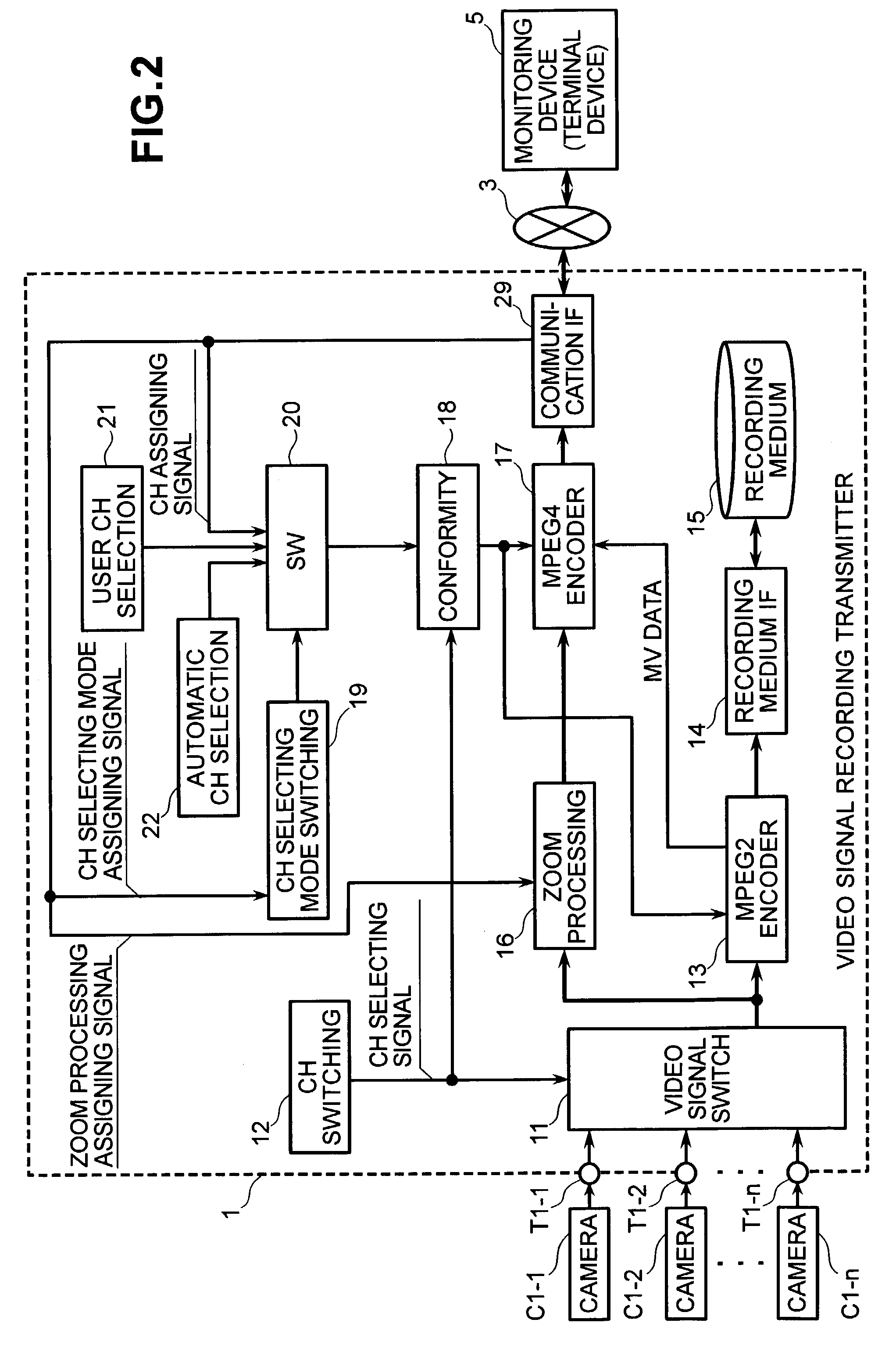
[0036]In this second embodiment, while the video signals of all the channels are normally sequentially switched as indicated by the above-described operation at an interval of e.g., several seconds, the video signals are transmitted to the monitoring device 5 at the remote location (in an automatic channel selecting mode), or the video signal of a specific fixed channel that is assigned by the user of the video signal recording transmitter is transmitted to the monitoring device 5 at the remote location (in a user channel selecting mode). When there is a channel assignment by the monitoring device 5 from the remote location, the video signal of the assigned channel can be transmitted to the monitoring device 5 at the remote location (in a monitoring device channel selecting mode).

[0037]A third embodiment of the monitoring system in accordance with the present invention will be explained next with reference to FIG. 3. FIG. 3 is a block diagram showing the third embodiment of the moni...

first embodiment

[0052]Similar to the first embodiment, the operation of the MPEG4 encoder 17 is controlled to perform compression-encoding processing when the discriminated regenerating channel and the channel assigned by the monitoring device 5 at the remote location conform to each other.

[0053]In this embodiment, it is possible to select which one of the video signal in real time produced by the camera and the past video signal regenerated from the recording medium 15 is to be sent to the monitoring device 5 at the remote location by the above-described operation, from the monitoring device 5 at the remote location. Further, it is possible to select whether the video signal in a selected position of the recording medium is regenerated and which channel of the regenerated video signal is transmitted to the monitoring device 5 at the remote location, from the monitoring device 5 at the remote location.

[0054]A fourth embodiment of the monitoring system in accordance with the present invention will b...

fourth embodiment

[0062]Namely, this embodiment is characterized in that an MPEG4 encoder function and a zoom processing function are provided in the camera device C1. The camera devices C1-1, C1-2, C1-n are respectively arranged in separate locations, and they are connected to each other by the LAN 7. In each of the camera devices C1-1, C1-2, C1-n, similar to the fourth embodiment, the video signal that is picked up through the lens C11 and the image sensor C12 is compressed and encoded in the MPEG2 format in the MPEG2 encoder C13, and it is changed to a packet. Thereafter, the video signal is recorded onto the recording medium 15 of the video signal recording transmitter 1 through the LAN interface C14 via the LAN 7. The video signal from each of the camera devices C1-1, C1-2, C1-n is recorded in time division.

[0063]The camera devices C1-1 to C1-n of this embodiment have a function for performing zoom processing with respect to the picked-up video signal in the zoom processing circuit C16 in accord...


PUM


Abstract

To mix video signals of plural channels in time division and record these video signals onto a recording medium, as well as to select and transmit the video signal of a specific channel to a terminal device at a remote location, there is a video signal switching unit for mixing the video signals of the plural channels in time division; a first video signal compressing unit for compressing the mixed video signals from the video signal switching unit; a unit for recording the video signal compressed by the first video signal compressing unit into the recording medium; second video signal compressing units for selecting a channel from the mixed video signals and compressing the video signals with a compressibility higher than that of the first video signal compressing unit; and a unit for transmitting the video signal compressed by the second video signal compressing unit to a remote location.

Description

BACKGROUND OF THE INVENTION[0001]The present invention relates to a video signal recording and transmitting device for compressing video signals of plural channels that are mixed in time division, recording the video signals onto a recording medium, and compressing the video signals using different compressibilities and transmitting these video signals to an external device.[0002]There is a monitoring system for recording a video signal, that has been produced by a camera located at a monitoring location, onto a recording medium, wherein the video signal is transmitted to a monitoring device from a remote location via a communication network. In such a monitoring system, it is necessary that the video signal to be recorded onto the recording medium is a video signal that is high in resolution and time resolution. However, it is necessary, when transmitting the video signal to a monitoring device at a remote location, to reduce the resolution and the time resolution in accordance wit...

Claims


Application Information

Patent Timeline
IPC IPC(8): H04N7/00G11B27/00H04N5/38H04N5/91H04N5/93H04N7/14H04N5/915H04N5/76H04N5/765H04N5/77H04N5/775H04N5/781H04N5/92H04N7/18H04N9/804H04N9/82H04N19/00H04N19/70
CPCH04N5/76H04N5/77H04N5/775H04N5/781H04N9/8042H04N9/8227H04N5/92
Inventor HORIUCHI, TADASUNISHIMURA, RYUJIKOMI, HIRONORIYAMAMOTO, NAOKI
Owner HITACHI LTD
Why Eureka
Try Eureka