Flow cell for measuring flow rate of a fluid using ultrasonic waves

a flow cell and ultrasonic wave technology, applied in the field of polymer based flow cells for ultrasonic flow meters, can solve the problems of inability to reversely detach the ultrasonic transducer from the flow cell, and achieve the effects of convenient detachment, convenient exchange, and convenient fastening

Active Publication Date: 2010-03-09
CYTIVA SWEDEN AB
View PDF23 Cites 45 Cited by
  • Summary
  • Abstract
  • Description
  • Claims
  • Application Information

AI Technical Summary

Benefits of technology

[0010]In the present invention the ultrasonic transducers (11) are substantially positioned in axial alignment, opposite each other, separated by a substantially straight part (12) of a flow cell channel (13). The ultrasonic transducers (11) are separated from the fluid inside the flow cell channel (13) by at least one plug (14), or a wall (15), to ensure that the ultrasonic transducers (11) do not come in direct contact with the fluid inside the flow cell channel (13). The ultrasonic transducers (11) are easily detachable from the flow cell (10) to facilitate exchange from a used flow cell (10) to a sterilised flow cell (10) between experiments, at a reasonable cost and within a reasonable time frame. In one embodiment of the present invention the ultrasonic transducers (11) are fastened to the flow cell (10) with the use of at least one bayonet joint (16) to facilitate easy fastening and detachment of the transducers (11), but other releasable fastening means, for easy attachment and / or easy detachment, are possible (e.g., snap fit, clip on, screw on).
[0011]The essentially straight part (12) of the flow cell channel (13) can have a length (L) between 3 and 30 cm, preferably between 10 and 25 cm, more preferably between 10 and 20 cm, even more preferably between 13 and 17 cm. The cross section of the channel (13) is typically shaped as a circle, but any geometry shape, for example a rectangle, should be considered to be within the scope of the present invention. In one embodiment of the present invention, the cross section of the channel (13) is shaped as a circle and the channel (13) has the form of a cylinder. The diameter (D) of the channel (13) can be between 1 and 16 mm, more preferably between 3 and 10 mm, even more preferably between 4 and 7 mm. Due to the axial alignment of the ultrasonic transducers (11) and the dimensions of the flow cell channel (13), i.e. cross sectional area and length of the flow cell channel (13), a flow meter using a flow cell (10) with dimensions falling within the above mentioned ranges fulfils the requirements: the flow meter accuracy is better than 5% at all flow rates within the range 25 ml / min up to 9 L / min. Furthermore, the backpressure from the flow cell (10) is less than 0.4 Bar for flow rates ranging from 25 ml / min up to 9 L / min (aqueous solutions). Additionally, the flow cell channel (13) geometry is designed to eliminate dead volume. Due to this, and also due to the selected proportions (i.e. cross sectional area and length) of the flow cell channel (13), the bandbroadening effect of the flow cell (10) according to the present invention has been calculated to be less than 10% for chromatographic separation operating at flow rates within the range 25 ml / min to 9 L / min.
[0012]In one aspect, the internal diameter of the essentially straight part (12) of the channel (13) changes by no more than 1%. The advantage of such a flow cell is that it need not be recalibrated every time that the flow cell is exchanged or replaced. This is particularly advantageous for flow cells which are used in disposable systems.
[0015]In one embodiment of the present invention, the flow cell (10) with the transducers detached is made of polymethylpentene (TPX polymethylpentene RT18XB, Mitsui Chemicals, Japan). Polymethylpentene (TPX) provides low damping of ultrasonic waves. Furthermore, polymethylpentene (TPX) is injection mouldable and inexpensive both as raw material and to process. Additionally, polymethylpentene (TPX) is USP VI classified which makes it suitable for use in systems operating in strictly regulated environments.
[0021]According to a second aspect of the present invention, there is provided a method for manufacturing a flow cell with the transducers detached as hereinbefore described wherein the flow cell is made by moulding. This is advantageous because it is an inexpensive and simple process. In one aspect, the flow cell with the transducers detached is made by is made by injection moulding. In another aspect, the channel (13) in the flow cell is made by drilling or by cutting.

Problems solved by technology

However, a further disadvantage with the existing ultrasonic flow meters having an axial alignment of the transducers is that the ultrasonic transducers are not reversibly detachable from the flow cell.

Method used


Image

  • Flow cell for measuring flow rate of a fluid using ultrasonic waves
  • Flow cell for measuring flow rate of a fluid using ultrasonic waves
  • Flow cell for measuring flow rate of a fluid using ultrasonic waves

Examples


second embodiment

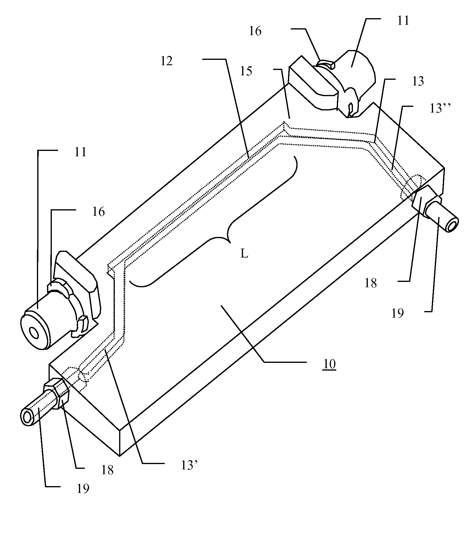
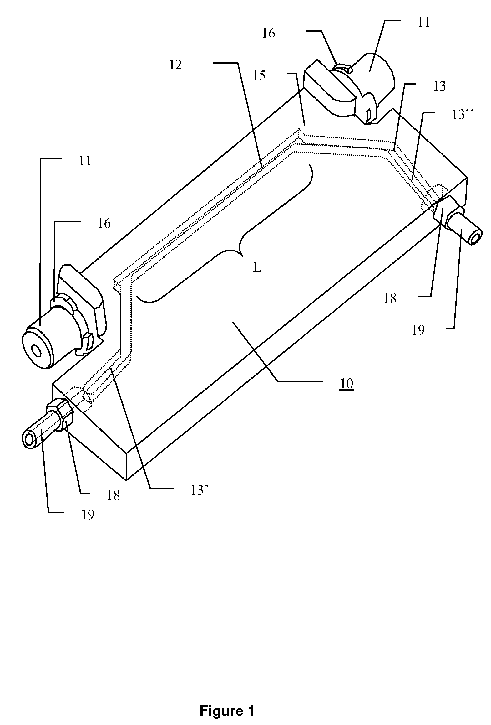
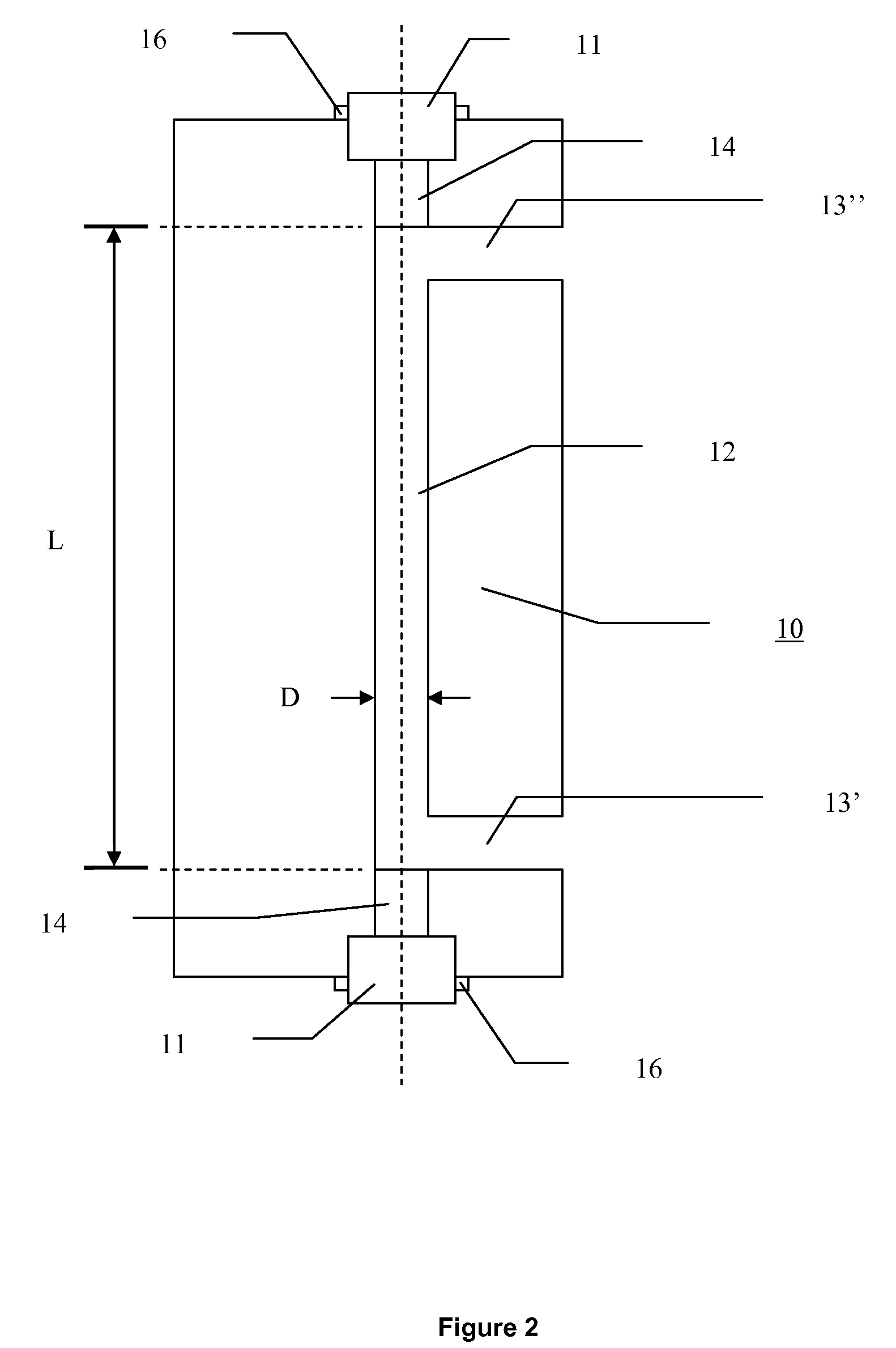
[0037]FIG. 2 is a schematic plan view of a flow cell (10) according to the present invention. The ultrasonic transducers (11) are positioned in alignment, opposite each other, separated by an essentially straight part (12) of a flow cell channel (13). The ultrasonic transducers (11) are positioned along the axis of the essentially straight part (12) of the flow cell channel (13). The ultrasonic transducers (11) are separated from the fluid inside the flow cell channel (13) by at least one plug (14), to ensure that the ultrasonic transducers (11) do not come in direct contact with the fluid inside the flow cell channel (13). The ultrasonic transducers (11) are detachable from the flow cell (10). The cross section of the channel (13) is typically shaped as a circle, but any geometry shape, for example a rectangle, should be considered to be within the scope of the present invention. In one embodiment of the present invention, the cross section of the channel (13) is shaped as a circle...

third embodiment

[0038]FIG. 3a) is an exploded perspective view of an ultrasonic flow meter according to the present invention. The figure shows ultrasonic transducers (11) and bayonet joints (16) for coupling to the flow cell (10) with plugs (14), connectors (18) for coupling of the flow cell (10) to another channel for liquid flow (19) and a sealing O-ring (20).

[0039]FIG. 3b) is a perspective view of the third embodiment of the ultrasonic flow meter according to the present invention. The figure shows ultrasonic transducers (11) and bayonet joints (16) for coupling to the flow cell (10), and connectors (18) for coupling of the flow cell (10) to another channel for liquid flow (19).

[0040]FIG. 3c) is a cross sectional view of the third embodiment of the ultrasonic flow meter according to the present invention. The figure shows a flow cell (10) with ultrasonic transducers (11) and bayonet joints (16) with plugs (14) for coupling to the essentially straight channel (12), and connectors (18) for coupli...


PUM


Abstract

The invention relates to a flow cell for an ultrasonic flow meter comprising two transducers of ultrasonic waves wherein the two transducers are reversibly detachable from the flow cell. The flow cell with the transducers detached is sterilisable and is particularly suitable for use in disposable or single-use systems.

Description

FIELD OF THE INVENTION[0001]The present invention relates to a polymer based flow cell for an ultrasonic flow meter and its manufacturing methods. The flow meter is suitable for use in disposable systems for analysis, purification or preparation of bio molecules like proteins and nucleic acids, for example by the use of chromatography or filtration.BACKGROUND OF THE INVENTION[0002]There is a large volume of literature related to ultrasonic flow meters. U.S. Pat. Nos. 2,874,568 and 2,923,155 describe ultrasonic flow meters in which the probes do not pierce the conduit wall, but rather are mounted external to the wall. With these arrangements the angle of refraction of the longitudinal wave at the interface between the conduit and fluid is relatively small and hence the ultrasonic waves have only a very minor velocity component in a direction parallel to the axis of fluid flow. With such systems, sensitivity, particularly to low flow rates, is a significantly limiting factor. In U.S. ...

Claims


Application Information

Patent Timeline
Patent Type & Authority Patents(United States)
IPC IPC(8): G01F1/66A01N1/02
CPCG01F1/662
Inventor EHRING, HANNOHERMANSSON, DAN
Owner CYTIVA SWEDEN AB
Why Eureka
Try Eureka