Unibody hydraulic nut

a technology of hydraulic nuts and nuts, which is applied in the direction of screws, load-modified fasteners, fastening means, etc., can solve the problems of inconvenient application of tensioning devices, inability to use hydraulic nuts, and additional exposure of field personnel to field personnel, so as to broaden the application, save time, and improve the effect of us

Active Publication Date: 2010-03-09
INTEGRA TECHNOLOGIES LTD
View PDF12 Cites 15 Cited by
  • Summary
  • Abstract
  • Description
  • Claims
  • Application Information

AI Technical Summary

Benefits of technology

[0013]The aim of this invention is to broaden the use of hydraulic nuts to be readily used along with sub-sea (ROV) and to broaden the applications where traditional hydraulic nuts will not fit due to small pitch spacing between studs and where additional time savings during flange assembly and disassembly are required.
[0014]Accordingly, an object of this invention is to improve the speed of assembly of bolted connections in underwater and other hazardous environments.
[0016]An additional object of this invention is to significantly speed up the assembly and disassembly process of bolted assemblies by requiring only a quick hydraulic connection and pressurization and eliminating the slow process of torquing, tensioning and heavy wrenching of nuts with a simple turn of a mechanical locking collar using a castellated socket or a small hand-held bar.
[0021]The unibody design of hydraulic nut (FIG. 3) combines 2 or more inner bodies (10) and mating studs (20) that are preferably simultaneously tensioned. The unibody construction reduces assembly times of bolted assemblies as it eliminates individual outer bodies and allows for thinner outer wall thickness as adjacent nuts share the same outer wall. This enables the use of hydraulic nuts in applications where there is a small pitch distance between each stud. The internal pressure port (16) connecting between each pressure area speeds up assembly by eliminating manual external connections found on individual hydraulic nuts. The unibody hydraulic nut is installed and bears (21) against the flange assembly, becoming part of the flange assembly.

Problems solved by technology

On certain flange assemblies with close bolt pitch, hydraulic nuts cannot be used as this diameter will not allow the hydraulic nut to be fitted without interference with adjacent hydraulic nuts.
In the field of nuclear reactors, this slow process will cause additional manrem exposure to field personnel.
These tensioning devices are not suitable in applications where assembly times measured in hours and minutes are cost prohibitive.
Also, the makeup of subsea flange assemblies is critical to ensure leak free connections and is a very time consuming process when using the above prior art.
Traditional hydraulic nuts and tensioners are not generally suitable for use by ROV.

Method used


Image

  • Unibody hydraulic nut
  • Unibody hydraulic nut
  • Unibody hydraulic nut

Examples


Embodiment Construction

[0047]With reference to the annexed figures, the preferred embodiments of the present invention will be herein described for indicative purposes and by no means as of limitations.

[0048]The figures and description attached to it are only intended to illustrate the idea of the invention. As to the details, the invention may vary within the scope of the claims. So, the size and shape of the unibody hydraulic nut may be chosen to best fit the flanges to connect.

[0049]Also, as used hereinabove and hereinafter, the term “stud” generally refers to stud, bolt, rod and other similarly shaped fasteners used in securing flanges assembly.

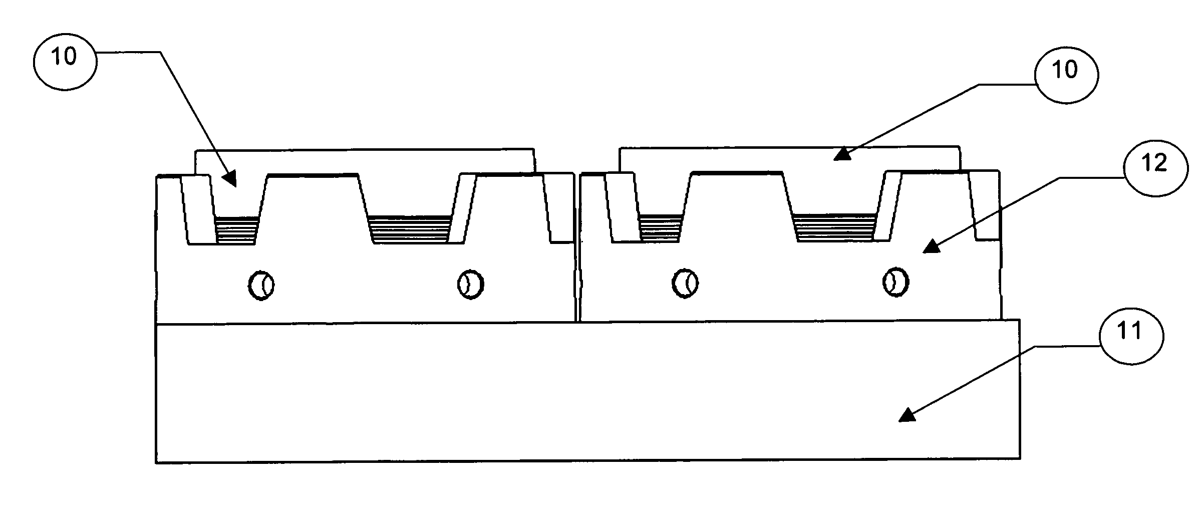
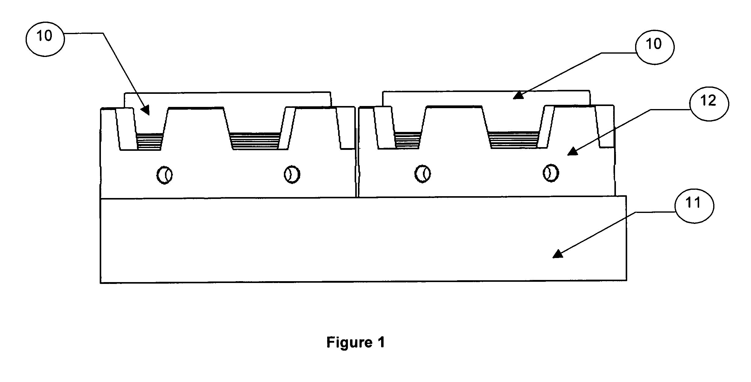
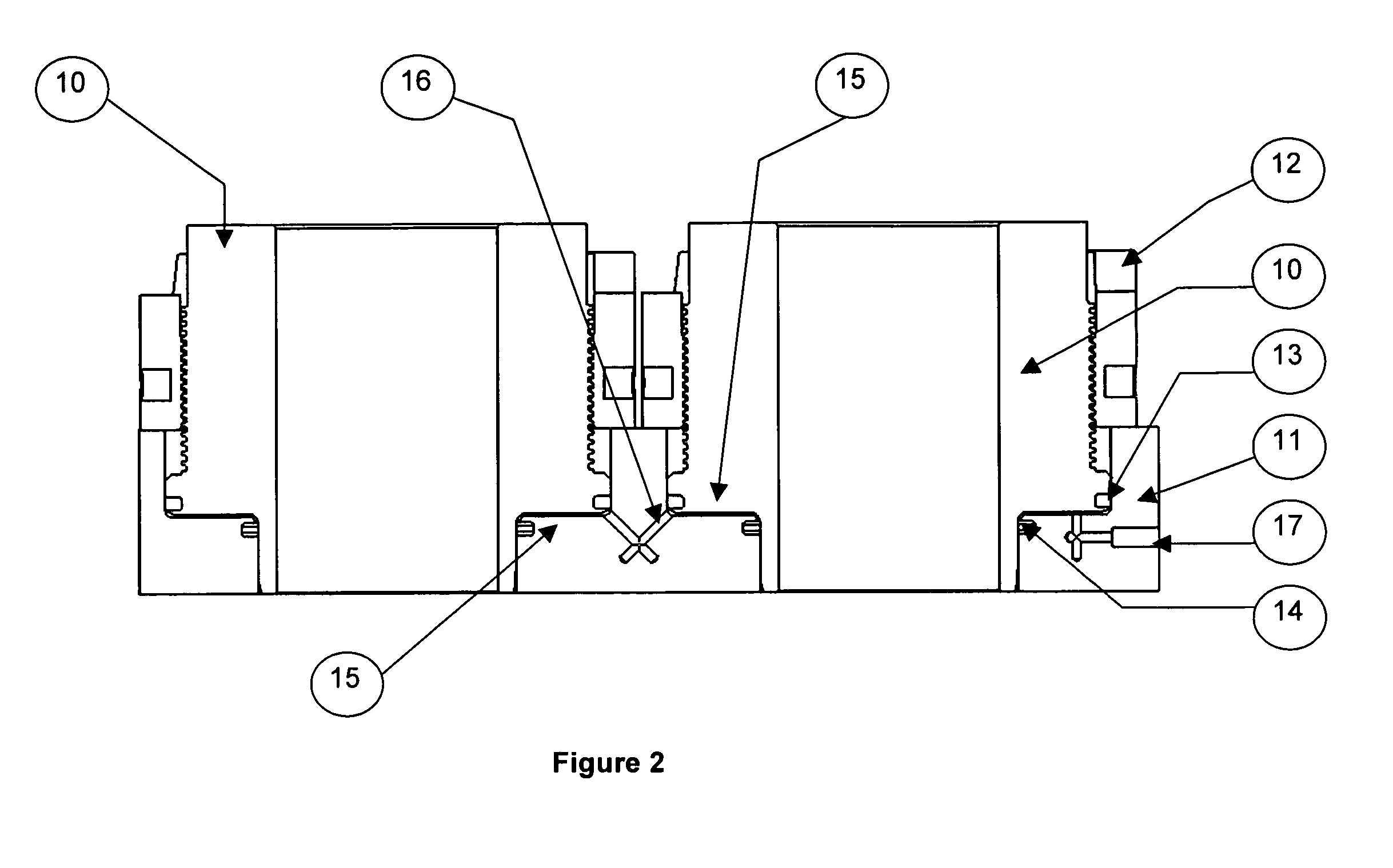
[0050]In accordance with the present invention, there is provided a hydraulic nut (FIGS. 1 to 6) for tensioning an assembly comprising an inner body (10), an outer body (11) matingly connected to two or more inner bodies, a locking collar (12) threaded on to each inner body (10), each locking collar (13) being preferably located adjacent to the outer body (11) ...


PUM


Abstract

A unibody hydraulic nut for tensioning multiple threaded fasteners includes an unibody containing two or more pistons to generate a clamping load, castellated locking collars with angled vertical castellations to engage a socket with matching castellations to enable easy turning by remotely operated means to capture the clamping load, internal hydraulic ports contained within the unibody linking each piston, seals to maintain the hydraulic pressure within the multiple annular pressure areas and an external hydraulic pressure port extending through the hydraulic nut unibody to the first pressure area and adapted to be connected to an external pressure source.

Description

CROSS-REFERENCE TO RELATED APPLICATIONS[0001]There are no cross-related applications.FIELD OF THE INVENTION[0002]The present invention relates to a hydraulic nut assembly. More specifically, the present invention is concerned with two or more hydraulic nuts that are contained within a common body to provide a load to two or more studs or bolts in an assembly.BACKGROUND OF THE INVENTION[0003]Hydraulic nuts are well known and have been used throughout the industry for many decades. Prior art includes individual nuts that are made up of an inner body that is threaded on to the stud to be tightened, an outer body that acts as a piston to generate an axial tension load to clamp the work pieces being joined and a locking collar to mechanically maintain the axial load generated by the hydraulic pressure in the annular piston created between the inner and outer bodies. The gap between the inner and outer bodies needs to be sealed so that hydraulic pressure is generated. This is achieved by ...

Claims


Application Information

Patent Timeline
Patent Type & Authority Patents(United States)
IPC IPC(8): E04G21/12
CPCF16B31/04F16B1/005F16B2200/89
Inventor BRITTON, GORDONHUGHES, DAVID
Owner INTEGRA TECHNOLOGIES LTD
Why Eureka
Try Eureka