
Wide-angle lens system

a wide-angle lens and system technology, applied in the field of wide-angle lens systems, can solve the problems of reducing resolution, affecting the accuracy of image identification, and reducing the degree of distortion, so as to achieve sufficient angle of view and less distortion

Inactive Publication Date: 2010-03-09
SAMSUNG ELECTRO MECHANICS CO LTD
View PDF5 Cites 28 Cited by
  • Summary
  • Abstract
  • Description
  • Claims
  • Application Information

AI Technical Summary

Benefits of technology

The design achieves a wide angle of view with reduced distortion, ensuring superior image quality and a smaller lens system size while effectively correcting various aberrations.

Problems solved by technology

Especially, a majority of wide-angle lens systems aiming at achieving a wide angle of view experience severe optical distortion, thus rendering it hard to identify an image of a peripheral portion of the lens system and represent perspective clearly.
This however does not ensure representation of perspective or degrades resolution.

Method used


Image

  • Wide-angle lens system
  • Wide-angle lens system
  • Wide-angle lens system

Examples


first embodiment

[0068]Table 1 below shows numerical values according to the first embodiment of the present invention.

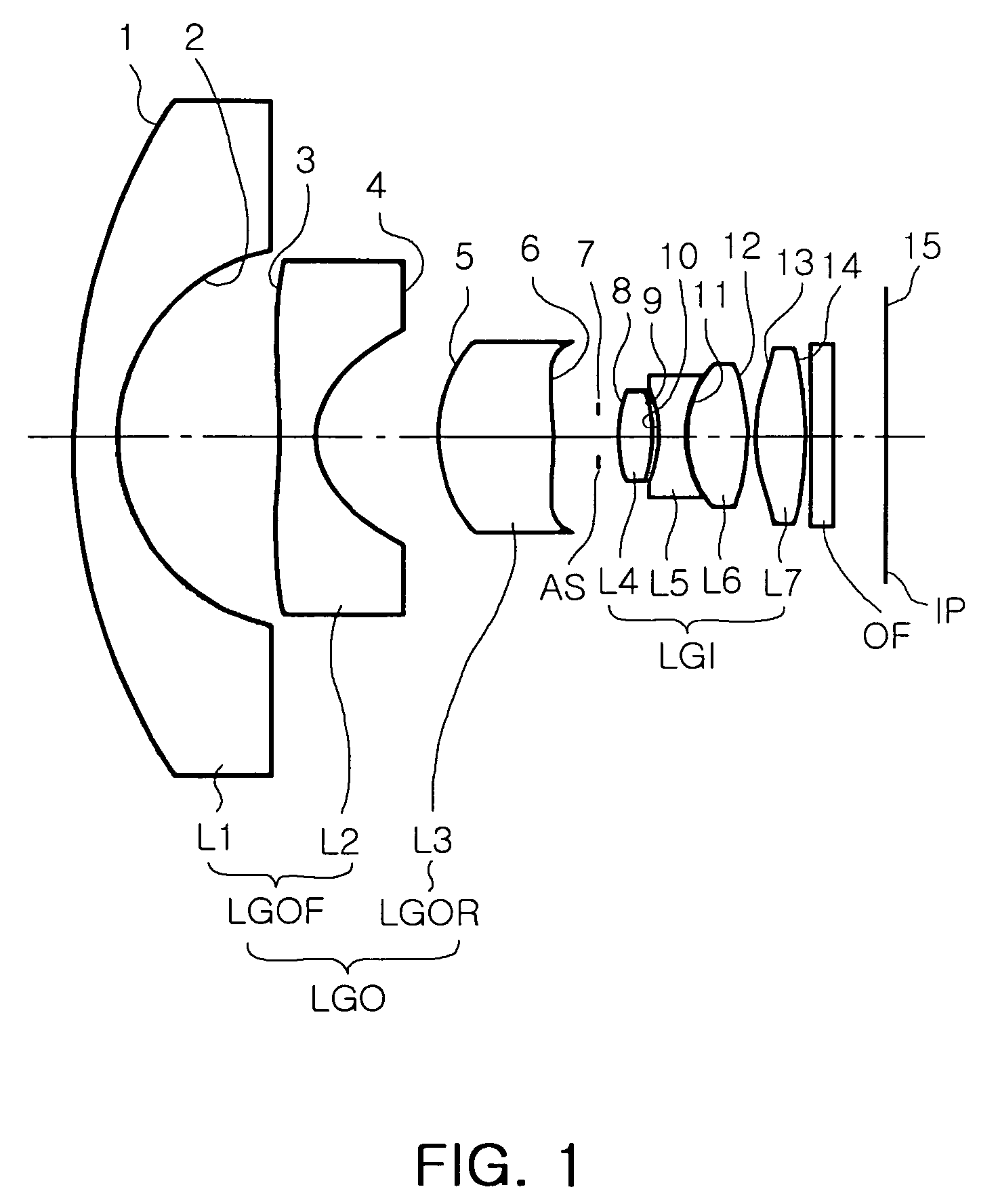
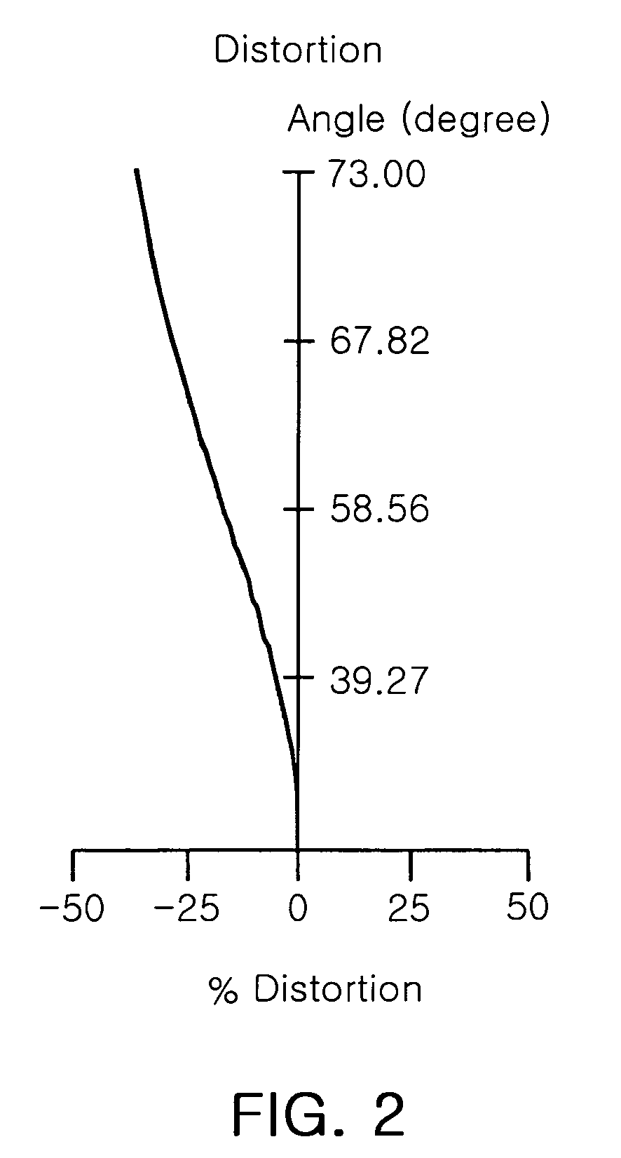
[0069]FIG. 1 is a view illustrating a lens arrangement of the wide-angle lens system according to the first embodiment of the present invention, and FIG. 2 is a graph illustrating distortion of the embodiment shown in FIG. 1.

[0070]In the first embodiment, an F number FNo is 2.0, an angle of view is 146 degrees, a total focal length F is 1.12 mm, a focal length FO of the object-side lens group LGO is 29.43 mm, a focal length FOF of the object-side lens part LGOF is −1.91 mm, a focal length FOR of the image-side lens part LGOR is 5.38 mm and a focal length FI of the image-side lens group LGI is 3.28 mm.

[0071]

TABLE 1SurfaceRadius ofThickness orRefractiveAbbeNo.curvature Rdistance tindex Ndnumber Vd115.61.11.640.824.84.0*3−17.50.91.556.0*41.83.0*53.62.81.623.6*6−50.01.27∞0.584.20.81.660.39−3.90.210−3.20.71.827.5112.81.51.660.312−4.80.2*134.31.31.556.0*14−5.21.3

[0072]In Table 1, * repres...

second embodiment

[0075]Table 3 below shows numerical values according to the second embodiment of the present invention.

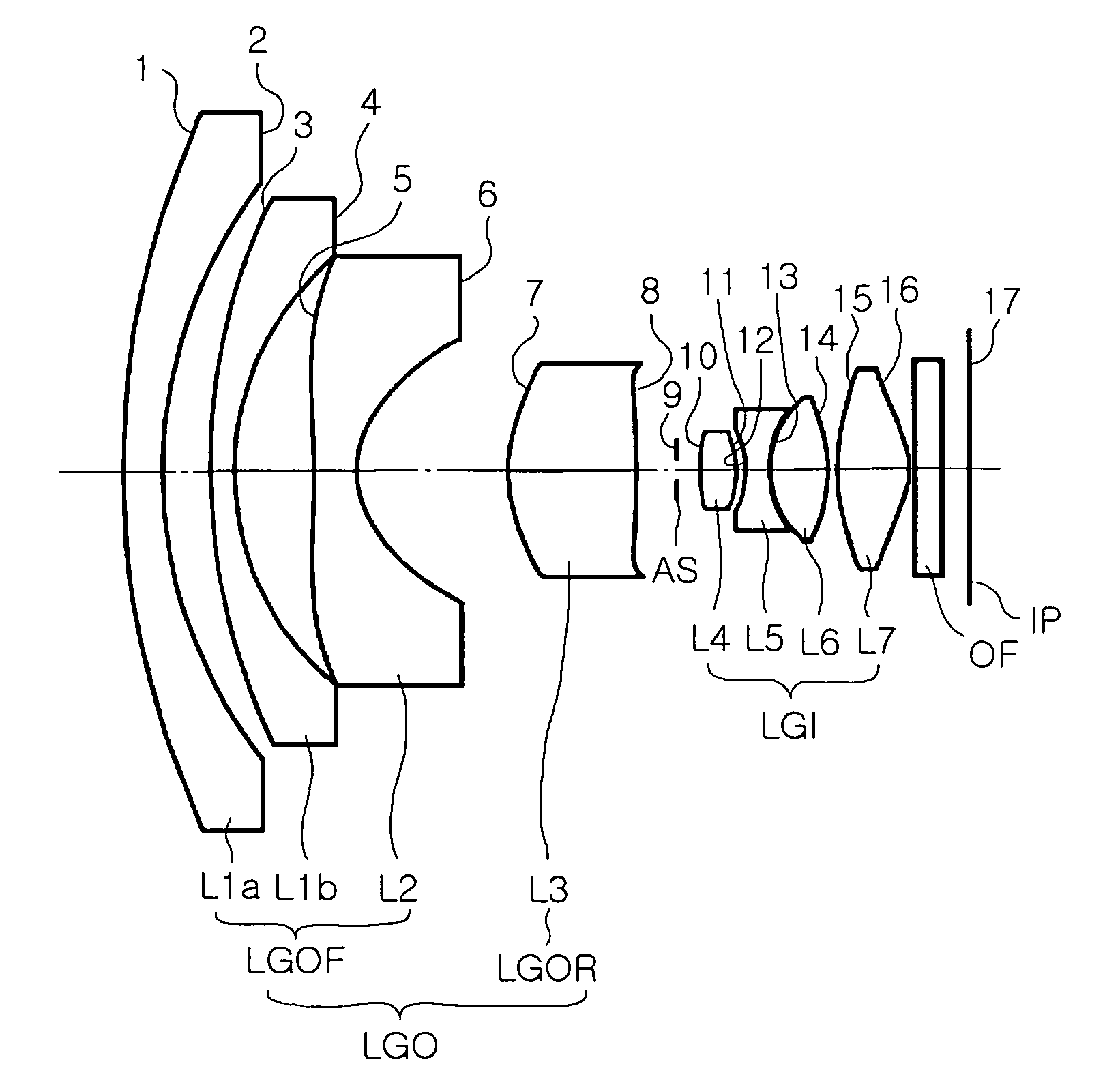
[0076]FIG. 3 is a view illustrating a lens arrangement of the wide-angle lens system according to the second embodiment of the present invention, and FIG. 4 is a graph illustrating distortion of the wide-angle lens system shown in Table 3 and FIG. 3.

[0077]In the second embodiment, an F number FNo is 2.5, an angle of view is 146 degrees, a total focal length F is 0.88 mm, a focal length FO of the object-side lens group LGO is 9.42 mm, a focal length FOF of the object-side lens part LGOF is −1.98 mm, a focal length FOR of the image-side lens part LGOR is 4.92 mm and a focal length FI of the image-side lens group LGI is 2.34 mm.

[0078]

TABLE 3Radius ofThickness orRefractiveAbbeSurface No.curvature Rdistance tindex Ndnumber Vd118.40.81.744.8210.01.0313.60.51.744.846.01.6*5−17.70.91.556.0*61.83.1*73.62.71.623.6*8−15.71.19∞0.3104.20.81.660.311−2.20.212−1.90.51.827.5132.01.21.660.314−3.60.2...


PUM


Abstract

There is provided a wide-angle lens system having a wide angle of view and less distortion. The wide-angle lens system including: an object-side lens group disposed at an object side with respect to an aperture stop and having overall positive refractive power; and an image-side lens group disposed at an image side with respect to the aperture stop and having overall positive refractive power, wherein a focal length ratio between the object-side lens group and the image-side lens group satisfies following condition 1,2<FO / FI<10  condition 1,where FO is a focal length of the object-side lens group (FO>0) and FI is a focal length of the image-side lens group (FI>0). This wide-angle lens system sufficiently corrects distortion even in a wide angle of view, thereby ensuring an image with superior quality.

Description

CROSS-REFERENCE TO RELATED APPLICATIONS[0001]This application claims the priority of Korean Patent Application No. 2007-0062721 filed on Jun. 26, 2007, in the Korean Intellectual Property Office, the disclosure of which is incorporated herein by reference.BACKGROUND OF THE INVENTION[0002]1. Field of the Invention[0003]The present invention relates to a wide-angle lens system, and more particularly, to a wide-angle imaging lens system for use in a camera installed in a vehicle, a camera for a mobile phone and a surveillance camera utilizing an imaging device such as a charge coupled device (CCD) or a complementary metal oxide semiconductor (CMOS).[0004]2. Description of the Related Art[0005]With a wide-angle lens system used more broadly and variously in a wide range of fields, for example for security or vehicle safety, diverse demands have arisen. Especially, a majority of wide-angle lens systems aiming at achieving a wide angle of view experience severe optical distortion, thus re...

Claims


Application Information

Patent Timeline
Patent Type & Authority Patents(United States)
IPC IPC(8): G02B9/06G02B9/04
CPCG02B13/0045G02B13/006G02B13/06G02B13/001
Inventor KIM, JIN JONGJUNG, MOON SIKJO, YONG JOO
Owner SAMSUNG ELECTRO MECHANICS CO LTD
Learn More