Bipod

a bipod and a lightweight technology, applied in the field of firearms, can solve the problems of not all bipods can quickly traverse and/or cant, and the bipods are typically heavy, and achieve the effect of convenient deploymen

Inactive Publication Date: 2010-03-16
TANGO DOWN
View PDF18 Cites 113 Cited by
  • Summary
  • Abstract
  • Description
  • Claims
  • Application Information

AI Technical Summary

Benefits of technology

[0006]One embodiment of the invention is a bipod for use with firearms including legs that stow near the firearm body and are easily deployed by rotating and / or extending them away from the firearm. One embodiment of the invention also includes a mounting system that allows the firearm to traverse and or cant.
[0007]One embodiment has legs that may be individually rotated using a ball lock system. One embodiment is arranged such that the operator presses a plunger and a leg rotates away from the firearm to deploy, or toward the firearm to stow the legs. A ball lock in one embodiment also contains a stop to prevent over rotation.
[0008]One embodiment has telescoping legs and contains an inner and outer component. The operator pulls on the inner leg to deploy it. One embodiment has a tab and button, which are integral parts of the inner legs, and allow the operator to adjust the height of the bipod as necessary. The button may also assist in holding the inner leg in a fully retracted position. One embodiment has a firearm mounting system, or rail clamp, which allows the firearm to traverse and / or cant without the use of adjustment tools. One embodiment has both a center swivel bolt, thereby allowing traverse movement, and a pivot, thereby allowing canting movement.

Problems solved by technology

Existing bipods are typically heavy and contain a multitude of parts.
Further, not all of them can quickly traverse and / or cant without the operator adjusting the position of the legs or loosening and retightening parts.

Method used


Image

  • Bipod
  • Bipod
  • Bipod

Examples


Embodiment Construction

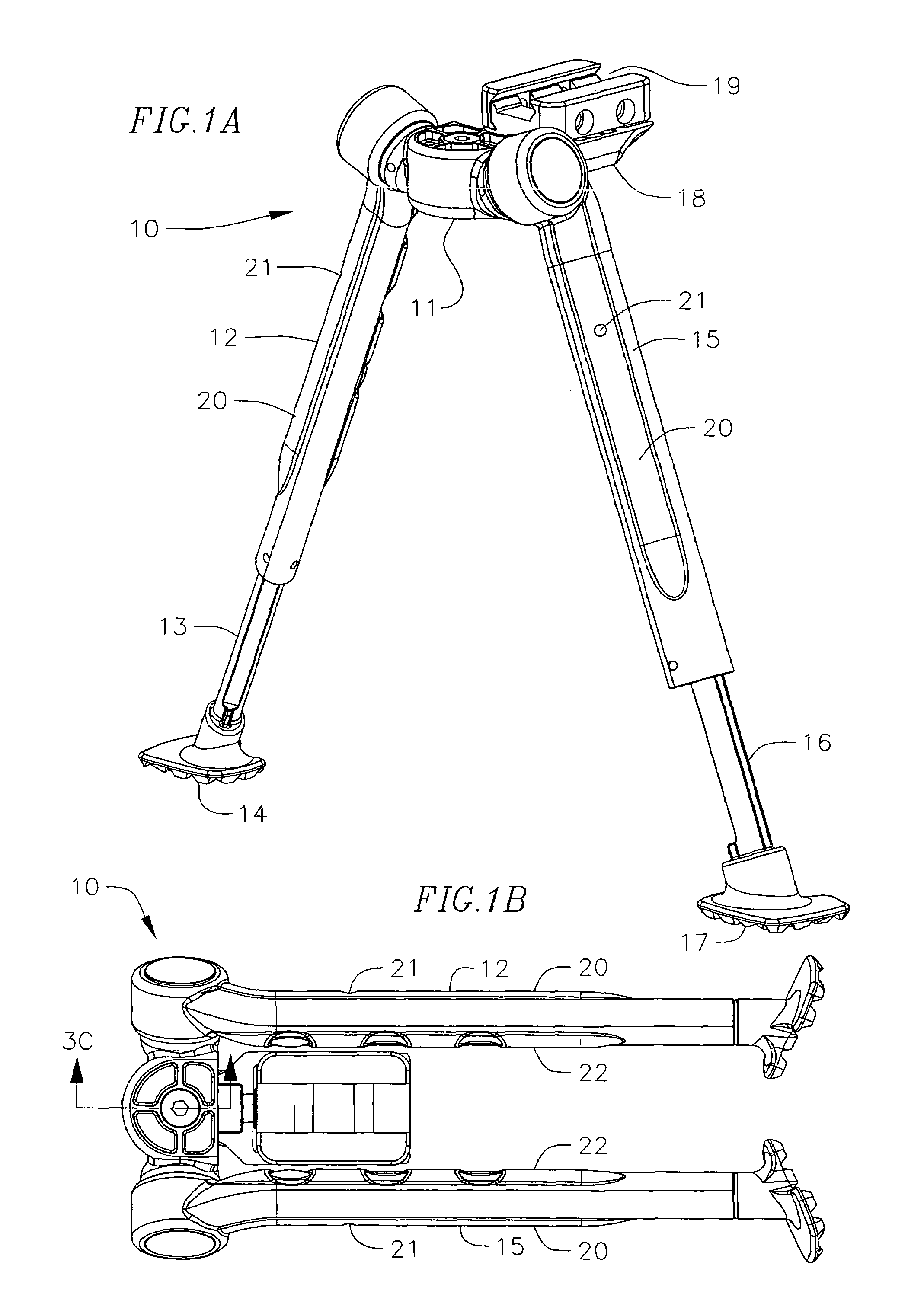
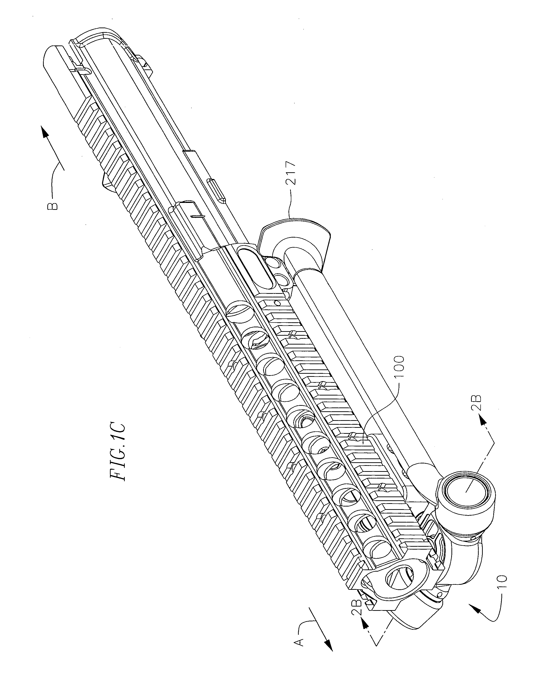
[0052]Referring to FIG. 1A, a bipod 10 according to one embodiment of the invention has two outer legs 12, 15, that are pivotally attached to a center swivel 11. A cantilevered rail clamp 19 dimensioned for receiving the rail 100 of firearm, is pivotally mounted to a base plate 18, which is in turn pivotally mounted to the center swivel 11. The bipod 10 is shown in a deployed condition with inner legs 13, 16 in a telescoped condition. FIG. 1B shows the bipod 10 in a stored condition with inner legs 13, 16 in a fully retracted condition inside of the outer legs 12, 15. FIG. 1C shows the bipod 10 in a stored condition while attached to a firearm rail 100. The bipod 10 in one embodiment is mounted to the firearm 100 such that in the stored position, the distal ends of the legs are oriented toward the muzzle of the firearm in the direction A depicted in FIG. 1C, or in the stored position such that distal ends the legs are oriented in direction B, away from the muzzle of the firearm.

[005...


PUM


Abstract

A bipod for a firearm is provided, including a body with cutouts to receive a bipod base, and a pair of legs. The bipod base is pivotally mounted to the body, and a firearm mounting bracket is pivotally mounted to the bipod base, allowing for a traversing and / or canting motion. A ball lock mounts each leg to the body, allowing the legs to be independently deployed or stored with the push of a plunger. The legs also telescope to allow adjustment of the bipod height.

Description

CROSS-REFERENCE TO RELATED APPLICATION[0001]This Application claims the benefit of U.S. Provisional Application Ser. No. 60 / 742,243, filed Dec. 4, 2005, which is incorporated herein by reference.FIELD OF THE INVENTION[0002]The present invention generally relates to firearms, and specifically to a lightweight bipod for use with machine guns.BACKGROUND OF THE INVENTION[0003]Taking a precision shot requires several constants. Among them are the ability of the shooter to acquire the appropriate sight picture, and the ability press the trigger straight to the rear without disturbing the sight picture. The weapon and ammunition should be capable of providing the shooter every advantage to take his best shot. The shooting position has to be stable, but stability is relative depending on the operating conditions. Prone is typically the most stable position, but not everyone's prone position is the same. Tactical and topographical considerations may also preclude the use of conventional pron...

Claims


Application Information

Patent Timeline
Patent Type & Authority Patents(United States)
IPC IPC(8): F41C27/22F16M11/06F41A23/10
CPCF16M11/16F16M11/26F41A23/10F41G11/003F16M2200/028F16M2200/08
Inventor CAHILL, JEFFREY M.BOWMAN, TIMOTHY J.
Owner TANGO DOWN
Why Eureka
Try Eureka