Coping apparatus and method of operation

a coping and coping technology, applied in the direction of sawing apparatus, sawing, sawing with straps, etc., can solve the problems of unsightly gaps, tedious and imprecise process, and not preferred miter joints

Active Publication Date: 2010-03-16
HOGAN THOMAS W +1
View PDF13 Cites 4 Cited by
  • Summary
  • Abstract
  • Description
  • Claims
  • Application Information

AI Technical Summary

Problems solved by technology

However, miter joints are not preferred for joining molding at internal 90° wall intersections.
This is because when both sections of molding are nailed or screwed to the wall the miter joint tends to separate with each piece of molding moving toward the wall rather than toward the adjoining section of molding as the sections are affixed to the wall by nails or screws, leaving an unsightly gap.
Those skilled in the art know that the formation of a coped butt joint using a coping saw for an ornate molding profile is a tedious and imprecise process of hand-cutting the end of the second section of molding.
Even a skilled craftsman may find it difficult to precisely follow a template or profiled line with a coping saw to form the perfectly coped butt joint.
While these conventional coping saws all employ various means for powering the blade, thus, easing the effort required by the user to cope a piece of molding, they all still appear to require significant user skill in following a given pattern necessary to make an accurately coped butt joint.
An additional drawback with the conventional automated coping saws is that coping many pieces of wood with a given pattern requires the user to follow a pattern for each cut.
Thus, the lack of repeatability is a significant drawback of the conventional automated coping saws.
However, such devices are unsuitable for coping a piece of wood because the required molding pattern is never a straight line.
Hydraulic paper cutters are only capable of cutting a straight line and not a curved pattern.
Hydraulic paper cutters are also not capable of cutting arbitrary coping patterns.
Furthermore, the characteristics of a stack of paper are very different from a strip of molded wood under shearing conditions.
For example, a strip of wood molding may have at least one surface that is not flat and thus could not be efficiently held down by hydraulic paper cutter shoes.
Additionally, a strip of wood molding may inelastically compress and / or splinter when sheared, unlike a stack of paper.

Method used


Image

  • Coping apparatus and method of operation
  • Coping apparatus and method of operation
  • Coping apparatus and method of operation

Examples


Embodiment Construction

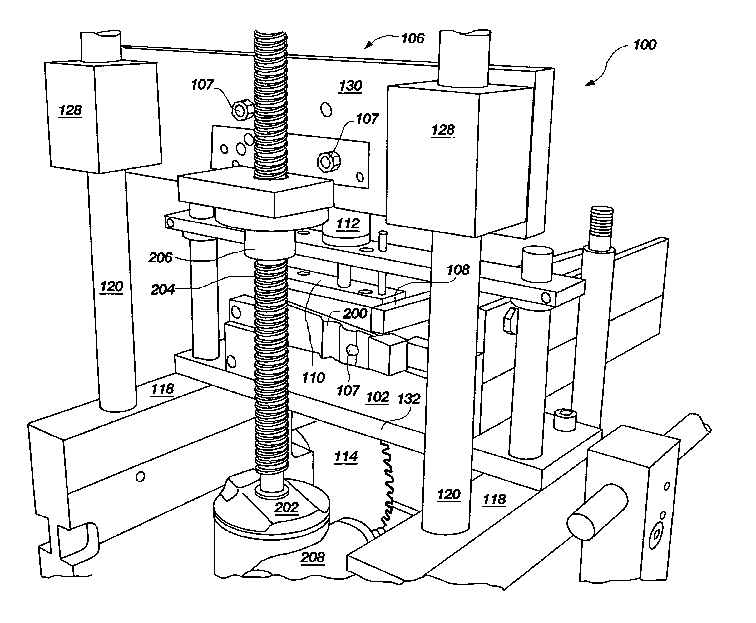
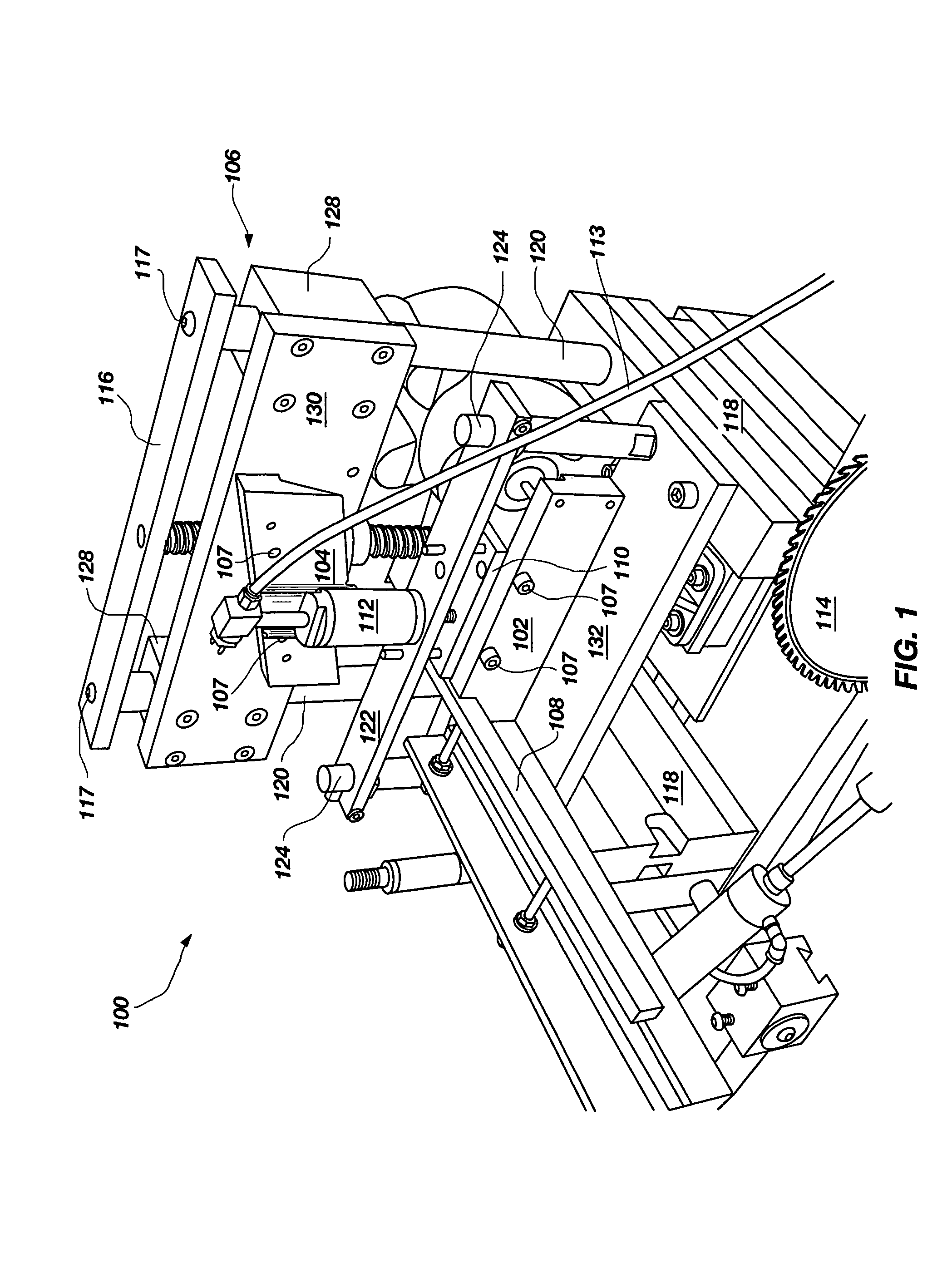
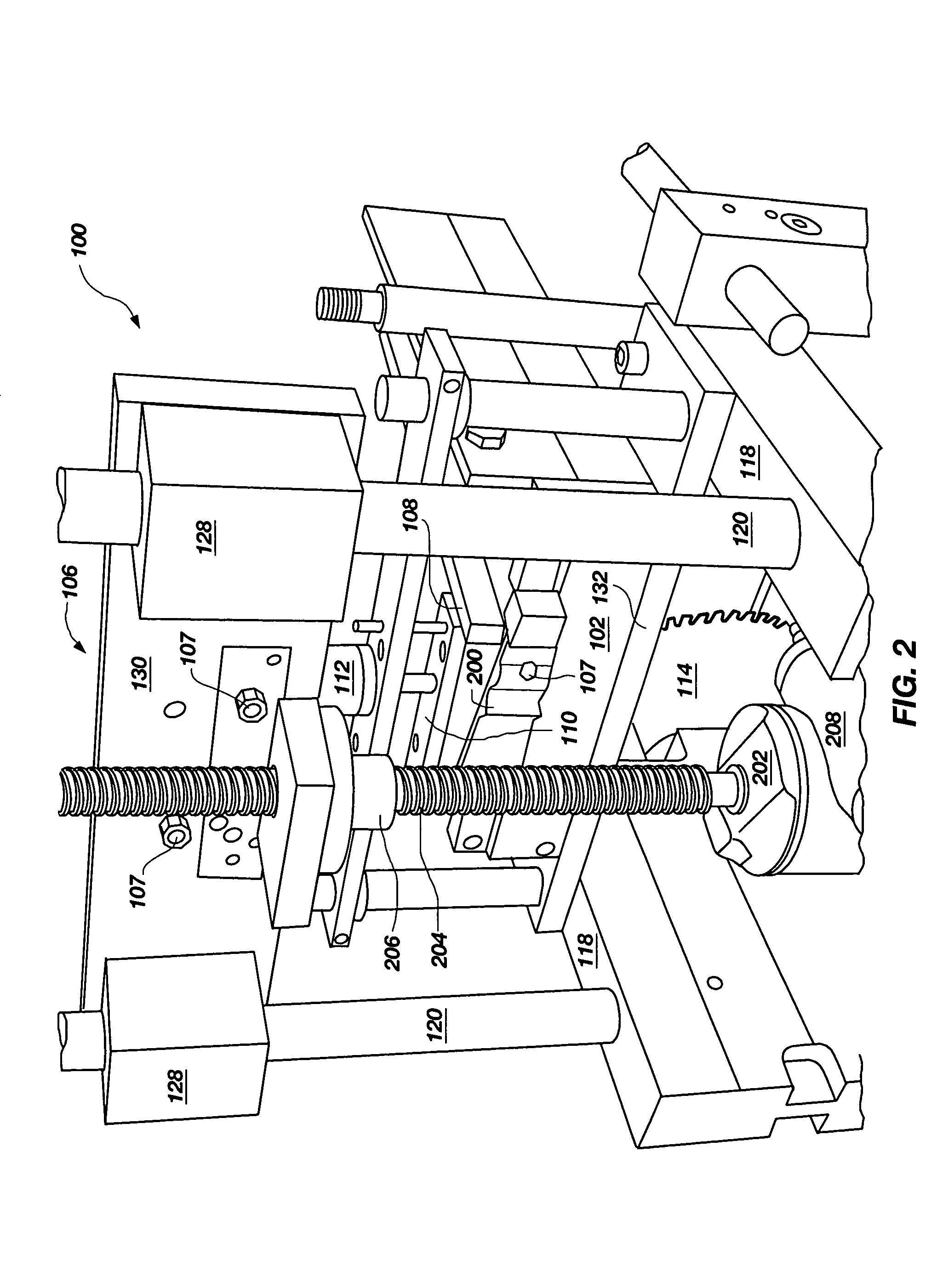
[0024]Embodiments of the present invention include a coping apparatus and method of operation that automates the process of forming coped butt joints for molding placed on internal wall angles that alleviates at least some of the problems associated with the use of miter joints or the time consuming use of conventional coping saws. Molding used with the embodiments of the present invention may be formed of any suitable wood or other suitable composite or decorative architectural material according to embodiments of the present invention. Exemplary woods of which moldings may be formed and from which coped butt joints may be cut include, for example and not by way of limitation, softwoods such as cedar and pine, and hardwoods such as alder, poplar, oak, cherry, walnut, maple and mahogany according to embodiments of the present invention. Other suitable materials that may be cut using the apparatus and methods of the present invention include medium density fiberboard (MDF) and high d...


PUM

PropertyMeasurementUnit
90° angleaaaaaaaaaa
angleaaaaaaaaaa
wall anglesaaaaaaaaaa

Abstract

Embodiments of the present invention include a coping apparatus and method of operation that automates the process of forming coped butt joints on strips of molding for placement on internal wall angles that alleviates at least some of the problems associated with the use of miter joints or time consuming hand or powered coping using conventional coping saws.

Description

CROSS-REFERENCE TO RELATED APPLICATION[0001]Pursuant to 35 U.S.C. § 119(e), this nonprovisional application claims benefit of priority to provisional patent application Ser. No. 60 / 631,739, filed Nov. 30, 2004, titled COPING APPARATUS AND METHOD OF OPERATION, the contents of which are herein incorporated by reference for all purposes as if fully set forth herein.BACKGROUND OF THE INVENTION[0002]1. Field of the Invention[0003]The present invention relates generally to woodworking equipment. More particularly, this invention relates to a profiled cutter or coping apparatus and method of operation.[0004]2. Description of Related Art[0005]Molding used in the construction of residential and commercial properties provides a decorative finish to ceiling / wall interfaces, floor / wall interfaces and along walls at table or chair height in rooms. Molding may have a plain finish with a straight profile or it may be decoratively shaped with an elaborate profile using a machine for forming the pro...

Claims


Application Information

Patent Timeline
Patent Type & Authority Patents(United States)
IPC IPC(8): B26D7/01B26D7/02
CPCB26D3/10B27F1/005B27G5/04B26D1/08B26D7/02Y10T83/7089Y10T83/748Y10T83/04Y10T83/7593Y10T83/7667
Inventor HOGAN, THOMAS W.HOGAN, JOHN M.
Owner HOGAN THOMAS W
Why Eureka
Try Eureka