FRP roofing material, manufacturing method, and its connecting structure and connecting method

a technology of roofing material and manufacturing method, which is applied in the direction of hollow wall articles, transportation and packaging, and other domestic objects, etc., can solve the problems of deterioration, increased weight per unit area, and difficulty in ensuring satisfactory strength and rigidity

Inactive Publication Date: 2005-09-13
TORAY IND INC
View PDF19 Cites 50 Cited by
  • Summary
  • Abstract
  • Description
  • Claims
  • Application Information

AI Technical Summary

Benefits of technology

[0018][a method of producing FRP roofing material where, in an RTM moulding method where channels are provided in the core material and the reinforcing fibre impregnated with a resin distributed through these channels, there is used an RTM moulding method employing a core material having through-holes];
[0019][a joint structure for FRP roofing material which is FRP roofing material where two or more FRP sandwich structures are butt joined and, as well as providing an FRP connecting layer extending across the surfaces of both ends of said sandwich structures, there is provided a layer containing a resin distribution medium between the abutting end faces]; and

Problems solved by technology

Hitherto, for constructing roofs or the eaves thereof, etc, roofing materials comprising a metal material such as a zigzag folded sheet affixed to a steel frame-based framework or roofing materials formed using concrete have been common, but where the chief structural material is a metal there is the problem of deterioration due to rusting.
Furthermore, since such roofing materials are composed of metal or concrete, they are heavy and, as well as this resulting in installation difficulties at the time of assembly, there are also, for example, disadvantages from the point of view of the earthquake resistance of the building when an earthquake occurs.
With metal, concrete or the like, if the weight is reduced, it then becomes more difficult to ensure satisfactory strength and rigidity.
However, in the case of precast concrete, the weight per unit area is very great, at approximately 250 kg / m2, so as well as installation being difficult there is also the problem that the effects on the base structure at the time of an earthquake are considerable, making it necessary for the building to have an unyielding base structure.
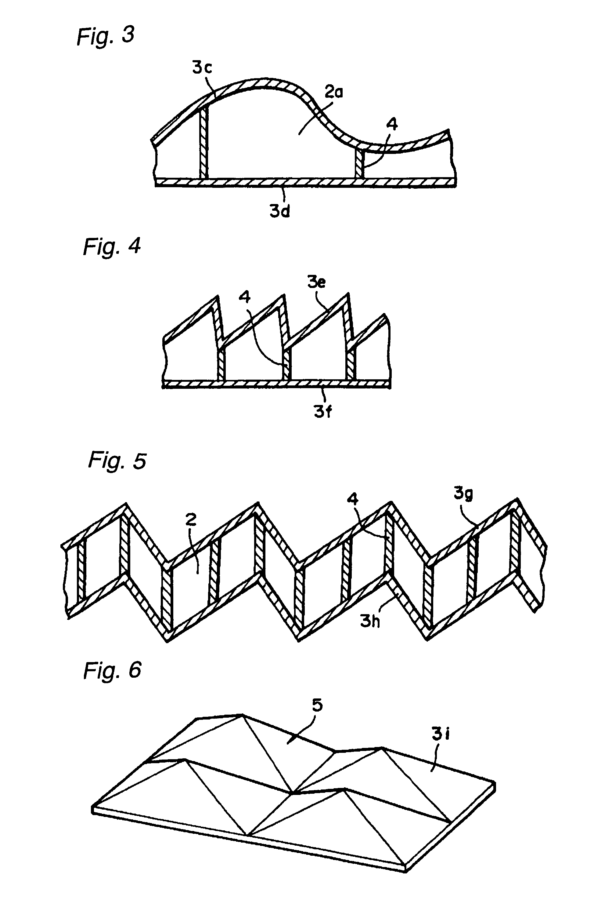
Furthermore, in the case of a roofing material construction where there has been affixed a metal material comprising a flat sheet or zigzag folded sheet, shaping into a curved surface or into a three-dimensional form is difficult, so there are considerable design limitations and there are restrictions in terms of improving the design by shaping the roofing material into a desired form.
Now, while FRP materials have been used hitherto for ships and other such large structures, practically no investigations have been conducted into their application as building materials with the exception of studies into their use merely as interior decorative materials or the like.
This is because FRP constructions in the shape of large structures have not been investigated in forms suitable as building materials and because associated factors relating to building materials, for example the fire-resistance and joint structures, etc, have not been fully investigated.
Furthermore, with regard to the method of forming a large structural material from an FRP, while there is the conventionally-known hand lay-up method, since the resin impregnation of the reinforcing fibre is carried out by hand in this method, the proportion of resin to reinforcing fibre in the FRP is very high and it is not possible to utilize the physical properties of the reinforcing fibre efficiently.
Moreover, because the resin is handled in the open, there are considerable problems in terms of the environment.
As a means for overcoming the above there is, for example, the RTM method where the resin is injected into a moulding tool in which reinforcing fibre has already been set, but there are problems in that it is necessary to apply pressure to the moulding tool and a very expensive moulding tool is required.
In the case of the phenolic resins which are particularly suitable for use in building material applications, it is difficult to obtain large integrally-moulded items using the above method.
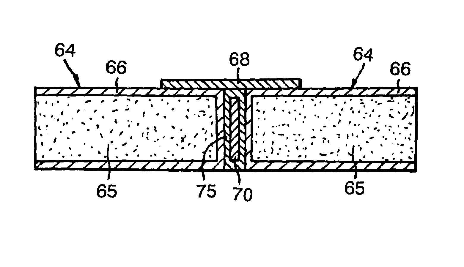
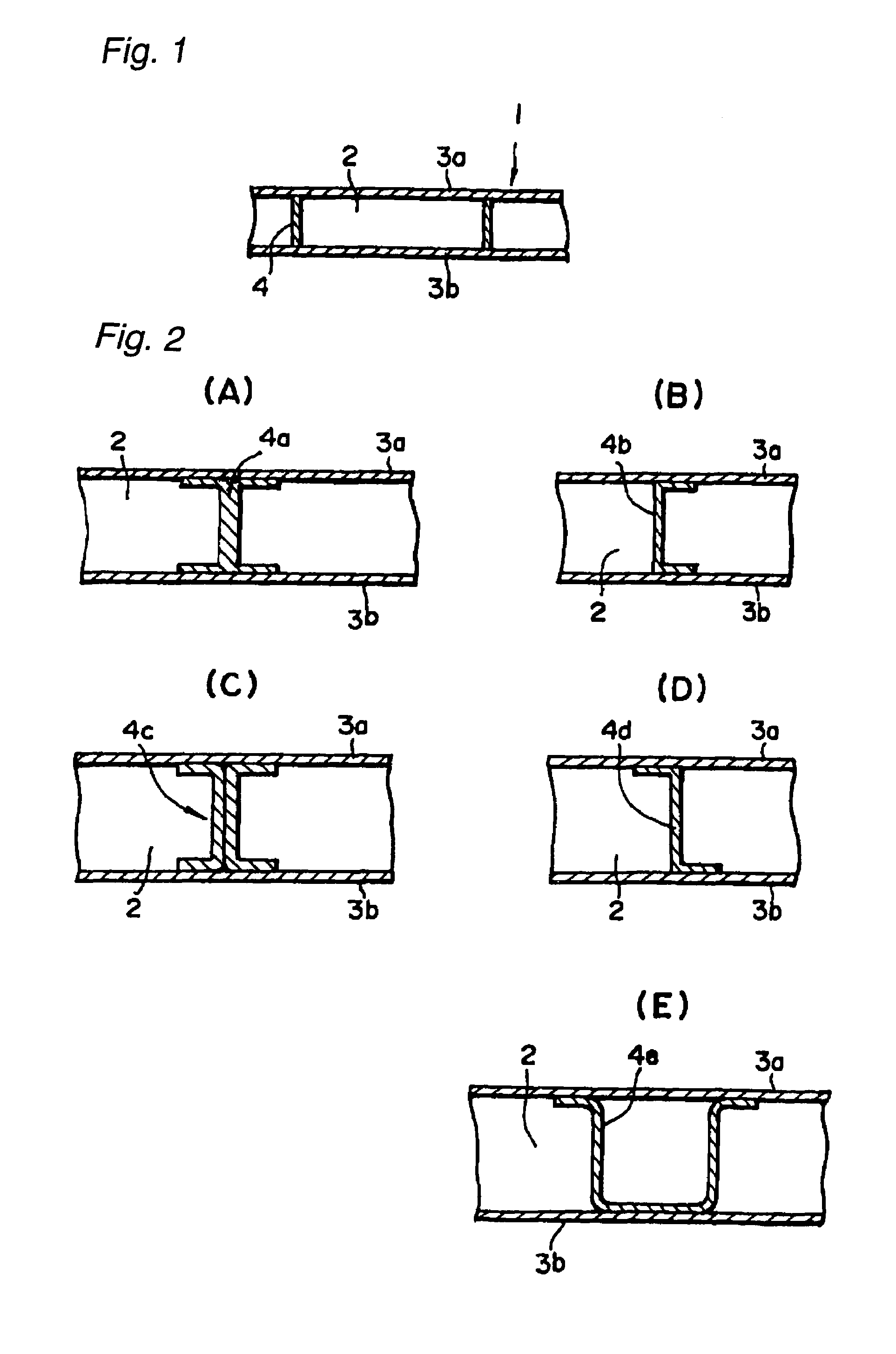
However, when joining FRP members to one another, in the case of the method of fastening using sheets arranged on the upper and lower surfaces as described above, it is necessary to provide holes in the FRP members passing through in their thickness direction, so problems arise in that the inherent strength of the FRP members is lowered and there is a risk of leaks occurring when used as a roofing material.
Thus, in the aforesaid joining method, the joint strength is governed by the compressive and shearing strengths of the FRP, and so large loads cannot be sustained.
On the other hand, in the case of joining using an adhesive, because the joining operation to assemble an FRP roof structure for example is generally an outdoor operation, the joining is very difficult to carry out reliably under such circumstances.
Furthermore, when carrying out re-roofing due to the deterioration of an existing roof such as that of a gymnasium, in order to protect the building itself from weather conditions of various kinds, there must be provided a temporary roof, and the provision of a temporary roof during prolonged work is both a technical problem and a problem in terms of cost.

Method used


Image

  • FRP roofing material, manufacturing method, and its connecting structure and connecting method
  • FRP roofing material, manufacturing method, and its connecting structure and connecting method
  • FRP roofing material, manufacturing method, and its connecting structure and connecting method

Examples


Embodiment Construction

[0069]Below, preferred practical forms of the present invention are explained with reference to the examples.

[0070]FIG. 1 shows a partial sectional view of FRP roofing material relating to a first embodiment of the present invention. In FIG. 1, FRP roofing material 1 has a rib structure 4 which joins together a pair of FRP sheets (skin layers) 3a, 3b arranged in parallel at a gap 2. In this practical embodiment, the rib structure 4 is also composed of FRP. However, it is possible for rib structure 4 to be composed of some other material such as metal or wood. Whatever material the rib structure 4 is composed of, it is desirable that the arrangement and incorporation thereof be carried out at the same time as the moulding of FRP sheets 3a, 3b.

[0071]Various shapes can be adopted as the sectional shape of the rib structure. FIG. 1 shows the cross-sectional shape of a rib structure 4 which simply extends vertically but various other shapes can be employed as shown in FIG. 2 for example...


PUM

PropertyMeasurementUnit
widthaaaaaaaaaa
lengthaaaaaaaaaa
thicknessaaaaaaaaaa

Abstract

This invention relates to fibre reinforced plastic (“FPR”) roofing materials with a sandwich structure. A pair of sheets of FRP are arranged with a gap between them, and a rib structure which joins the sheets is interposed. Further, this invention relates to a method for producing FRP roofing material in which channels are provided in the core material and a reinforcing fibre impregnated with a resin is distributed through these channels. A preferred joint structure for the roofing material is to use butt joints and to provide a connecting layer extending across the surfaces of both ends of the sandwich structures. A layer containing a resin distribution medium is provided between the abutting end faces. This invention overcomes various problems of conventional joint structures, permitting the ends of the sandwich structures to be easily, firmly and cheaply joined together, ensuring high joint strength and rigidity, while achieving excellent appearance.

Description

TECHNICAL FIELD[0001]The present invention relates to an FRP roofing member and manufacturing method, and connecting structure and a connecting method therefor, and, in particular, it relates to an FRP roofing member of large area which is light in weight, has excellent installation characteristics, high durability and outstanding design properties, and which can also be connected together.TECHNICAL BACKGROUND[0002]Hitherto, for constructing roofs or the eaves thereof, etc, roofing materials comprising a metal material such as a zigzag folded sheet affixed to a steel frame-based framework or roofing materials formed using concrete have been common, but where the chief structural material is a metal there is the problem of deterioration due to rusting. Furthermore, since such roofing materials are composed of metal or concrete, they are heavy and, as well as this resulting in installation difficulties at the time of assembly, there are also, for example, disadvantages from the point ...

Claims


Application Information

Patent Timeline
Patent Type & Authority Patents(United States)
IPC IPC(8): B29C65/00B29C70/04B29C70/08B29C70/48B29C70/54E04B7/22E04B7/00E04D3/35E04C2/26E04B7/10E04C2/296E04C2/34E04D3/24E04D3/28
CPCB29C66/1142B29C66/721B29C66/723B29C70/088B29C70/48B29C70/547E04B7/107E04B7/22E04C2/296E04C2/34E04D3/28E04D3/35E04D3/352E04D3/357B29C66/14B29C65/00B29C66/727B29L2024/00Y10T428/24744Y10T428/24273Y10T428/24322Y10T428/24661Y10T428/24628B29C65/02B29C65/5028B29C65/562B29C66/112B29C66/114B29C66/131B29C66/43B29C66/438B29C66/71B29C66/7212B29C66/72141B29K2307/04B29K2309/08B29K2061/04E04B1/665E04B1/941E04B7/102E04D3/32
Inventor KONDO, TOSHIYUKIITO, TOSHIHIROMATSUURA, MASASHI
Owner TORAY IND INC
Why Eureka
Try Eureka