Mission replaceable rotor blade tip section

a technology of rotor blade and tip section, which is applied in the direction of rotors, marine propulsion, vessel construction, etc., can solve the problems of reducing the service life of the rotor blade. , to achieve the effect of reducing the number of structural components, and ensuring the smooth surface of the blad

Active Publication Date: 2006-05-18
SIKORSKY AIRCRAFT CORP
View PDF18 Cites 52 Cited by
  • Summary
  • Abstract
  • Description
  • Claims
  • Application Information

AI Technical Summary

Benefits of technology

[0009] Another main rotor blade includes a spar interface section that slides through openings in the blade spar and tip spar leading edges. Ramped spar interface sections engage respective ramped blade spar transition surfaces and ramped tip spar transition surfaces to provide a mechanical interlock in addition to a multiple of fasteners which are recessed below a respective upper blade spar surface a lower blade spar surface, a tip spar section upper surface and a tip spar section lower surface. A fairing which corresponds to the rotor blade shape covers a butt joint between the blade spar, tip spar, and the fasteners to provide a smooth aerodynamic blade surface.
[0010] The present invention therefore provides a replaceable rotor blade tip section that is applicable to anhedral form, minimizes the number of structural components, yet may be readily replaced to tailor the main rotor blade tip end geometry to accommodate specific mission requirements.

Problems solved by technology

Rotor blade tip sections are subjected to the greatest stresses / strains due to aerodynamic forces, and concomitantly experiences the greatest structural degradation due to wear and abrasion (due to the high rotational velocity of the main rotor blade tip), during operation of the helicopter main rotor assembly.
Typically, only a very end portion of a main rotor blade tip is designed to be replaceable since the tip portion is most susceptible to damage caused by erosion and solid object strikes.
The length of the replaceable portion of conventional rotor blade tip sections is generally limited by the strength of the attachment joint.
This approach makes replacement of the complex geometry portion of the blade tip relatively difficult while requiring extensive labor in a significant manufacturing facility type to accomplish replacement.
One dilemma is that a single tip end geometry will not satisfy all mission profiles.

Method used


Image

  • Mission replaceable rotor blade tip section
  • Mission replaceable rotor blade tip section
  • Mission replaceable rotor blade tip section

Examples


Embodiment Construction

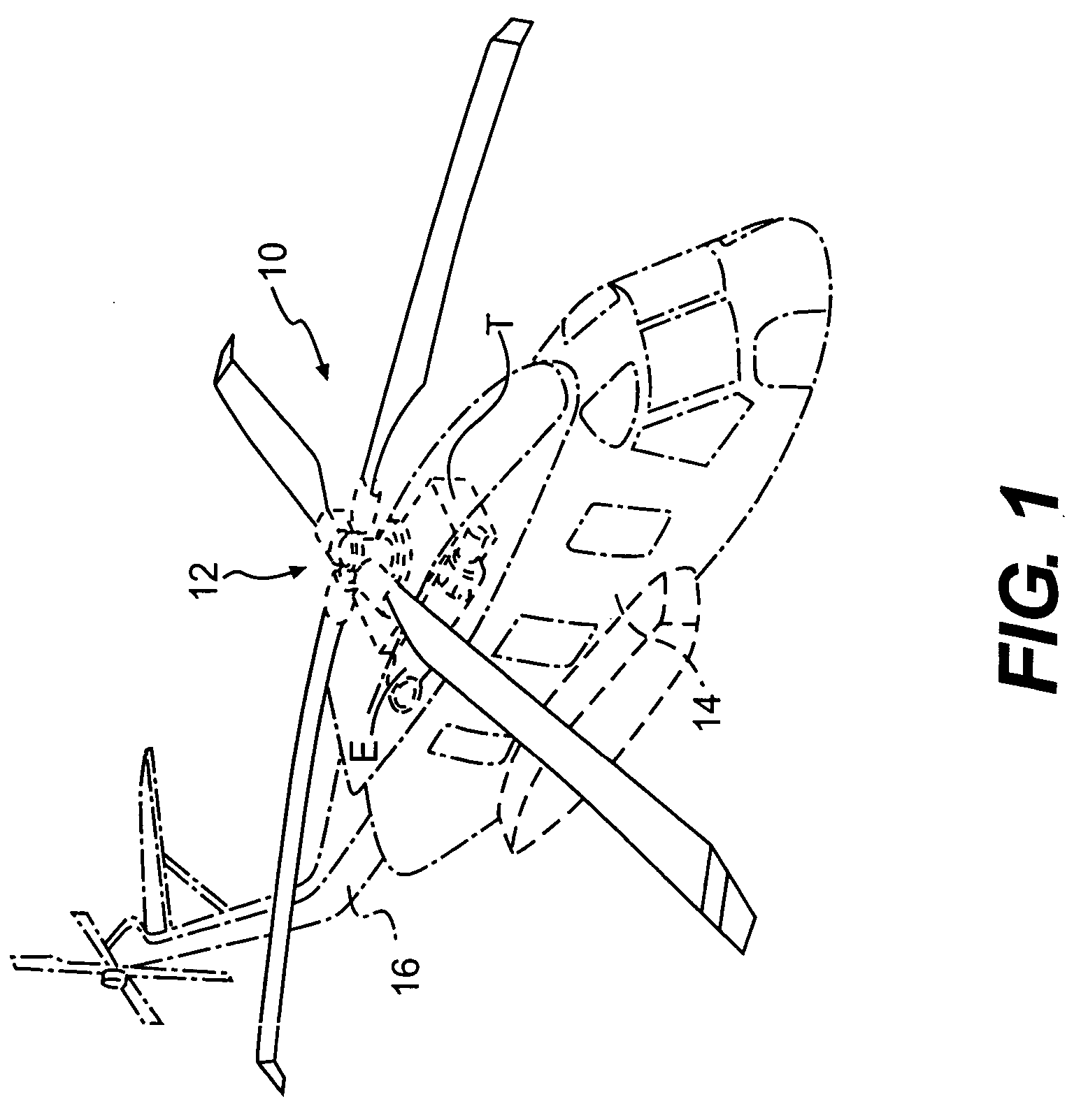
[0021]FIG. 1 schematically illustrates a rotary-wing aircraft 10 having a main rotor assembly 12. The aircraft 10 includes an airframe 14 having an extending tail 16 which mounts an anti-torque rotor 18. The main rotor assembly 12 is driven through a transmission (illustrated schematically at T) by one or more engines E. Although a particular helicopter configuration is illustrated in the disclosed embodiment, other machines such as turbo-props, tilt-rotor and tilt-wing aircraft will also benefit from the present invention.

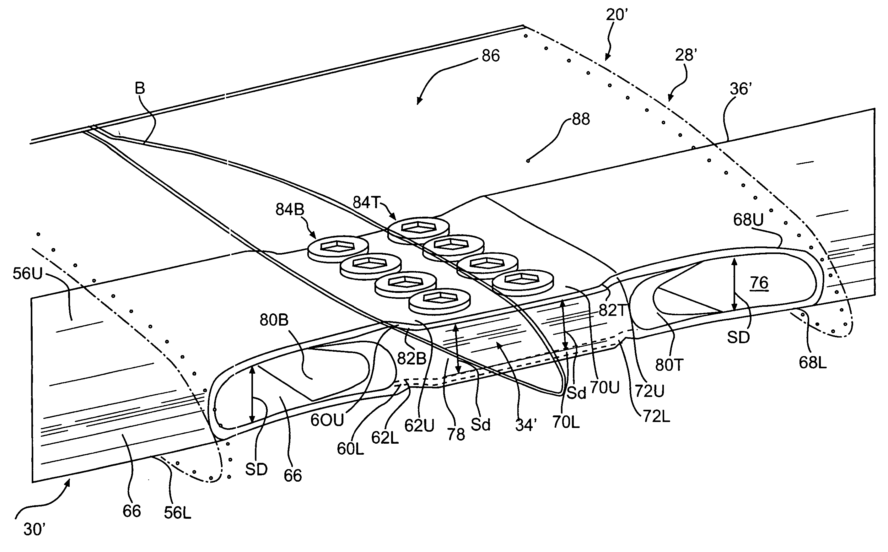
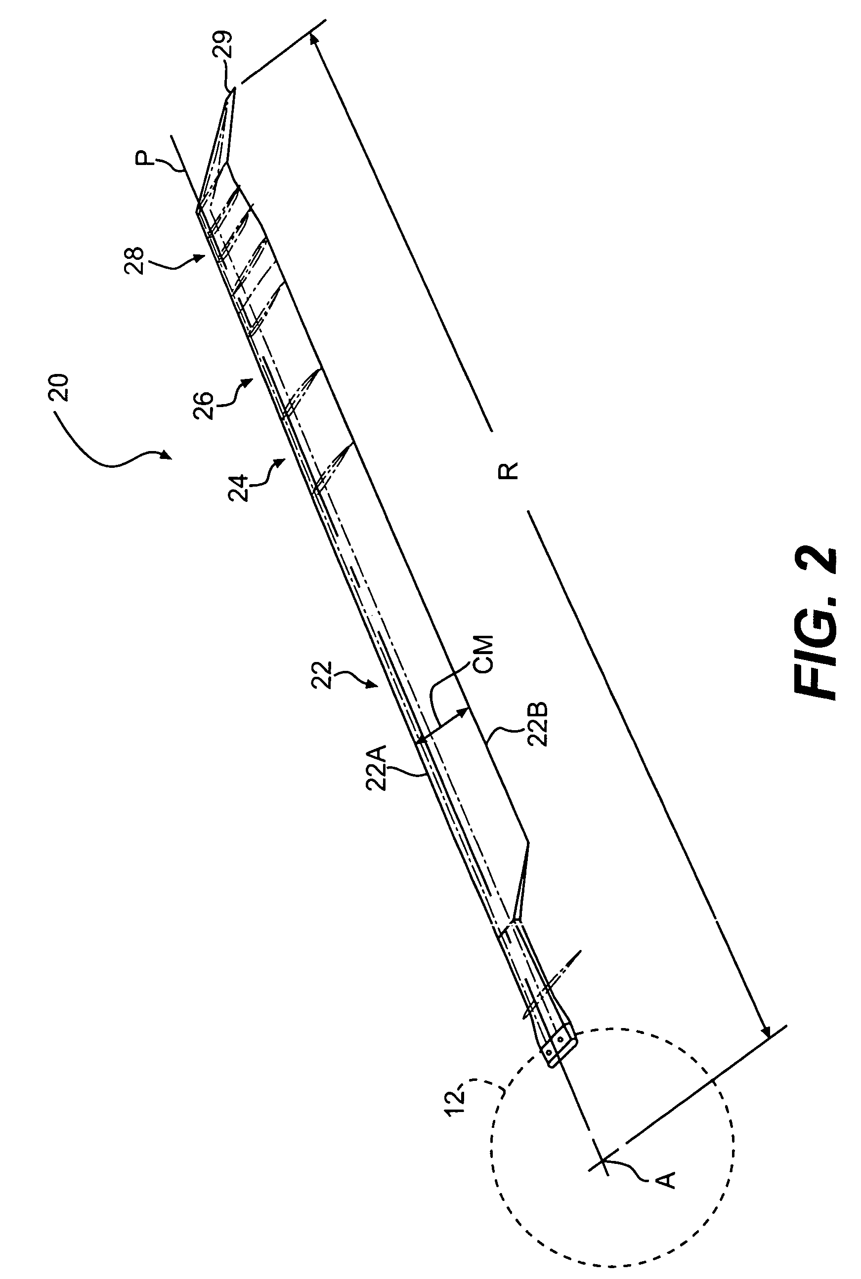
[0022] Referring to FIG. 2, a rotor blade 20 (only one illustrated) of the rotor assembly 12 includes an inboard section 22, an intermediate section 24, and an outboard section 26. The inboard, intermediate, and outboard sections 22, 24, 26 define the span of the main rotor blade 20. The rotor blade sections 22, 24, 26 define a blade radius R between the axis of rotation A and a distal end 29 of a replacement blade tip section 28. The rotor blade 20 further defin...


PUM


Abstract

A rotor blade includes a removable blade tip section which is mounted to an outboard rotor blade section by mechanically mounting a tip spar to a main blade spar with a spar interface section which bridges a butt joint between the blade spar and the tip spar. The spar interface section is mounted within the blade spar and the tip spar with a multiple of threaded fasteners which are under shear load during rotor blade rotation.

Description

BACKGROUND OF THE INVENTION [0001] The present invention relates to a rotary wing aircraft rotor blade, and more particularly to a replaceable tip section therefor. [0002] Conventional rotary wing aircraft rotor blades often include an anhedral tip section of a selected sweep, taper, and form to improve the blade performance. Anhedral tip sections increase hover performance and lift capabilities of a rotary wing aircraft on which the blades are fitted without increasing the structural features of the main rotor hub and spindle. [0003] Rotor blade tip sections are subjected to the greatest stresses / strains due to aerodynamic forces, and concomitantly experiences the greatest structural degradation due to wear and abrasion (due to the high rotational velocity of the main rotor blade tip), during operation of the helicopter main rotor assembly. These forces are only increased upon a tip section which utilizes an anhedral or other non-straight form. [0004] Typically, only a very end por...

Claims


Application Information

Patent Timeline
Patent Type & Authority Applications(United States)
IPC IPC(8): B64C11/00
CPCB64C27/463B64C27/467B64C27/473B64C2027/4736B64C2211/00
Inventor KOVALSKY, DAVID A.VIOLA, KEVIN P.
Owner SIKORSKY AIRCRAFT CORP
Why Eureka
Try Eureka