Engine assembly for aircraft comprising an engine and a mounting device for such an engine

a technology of mounting device and engine, which is applied in the direction of machine supports, transportation and packaging, and other domestic objects, can solve the problems of premature wear of the engine, affecting the life and performance of the engine, and inevitably occurring high friction, so as to reduce the torque, improve the resistance to thrust forces, and the engine life and performance is no longer reduced

Inactive Publication Date: 2010-03-16
AIRBUS OPERATIONS (SAS)
View PDF8 Cites 26 Cited by
  • Summary
  • Abstract
  • Description
  • Claims
  • Application Information

AI Technical Summary

Benefits of technology

[0016]Advantageously, the mounting system according to the invention is provided with mounting means that considerably improve resistance to thrust forces compared with what is possible according to prior art using the conventional solution of lateral connecting rods, since this device can considerably reduce the torque about the transverse axis applied to the engine and related to these thrust forces without it being necessary to use lateral connecting rods.
[0017]Consequently, during aircraft cruising phases, the specific positioning of the two aft half-fasteners resisting thrust forces implies that there is practically no longitudinal bending on the engine. In this way, no premature wear of engine components is observed, and therefore the life and performances of the engine are no longer reduced.
[0018]Longitudinal bending of the engine due to thrust forces is eliminated firstly by the fact that these forces are resisted by the aft fastener alone and no longer using the resisting device as was the case before, at the horizontal plane passing through the longitudinal axis of the engine which is very advantageous since thrust forces are generated along the longitudinal axis of this engine.
[0022]Preferably, the two branches of the fork jointly form a half-ring, this shape being preferred so as to limit disturbances of the gas flow output from the annular fan duct. To achieve this, this half-ring is preferably centered on the longitudinal axis of the engine.

Problems solved by technology

In a first case in which no particular precautions have been taken for the observed bending, high friction inevitably occurs firstly between rotating blades of the fan and the fan casing, and secondly between the rotating blades of the compressor and the turbine and the engine central casing.
The main consequence of this friction is then premature wear of the engine which is obviously prejudicial to its life and performances.
It has been observed that mounting means according to prior art, and more precisely their thrust resistance devices, are incapable of satisfactorily limiting the longitudinal bending of the engine due to torque about the transverse axis related to thrusts, particularly during aircraft cruising phases.

Method used


Image

  • Engine assembly for aircraft comprising an engine and a mounting device for such an engine
  • Engine assembly for aircraft comprising an engine and a mounting device for such an engine
  • Engine assembly for aircraft comprising an engine and a mounting device for such an engine

Examples


first embodiment

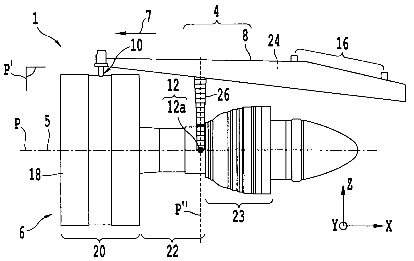
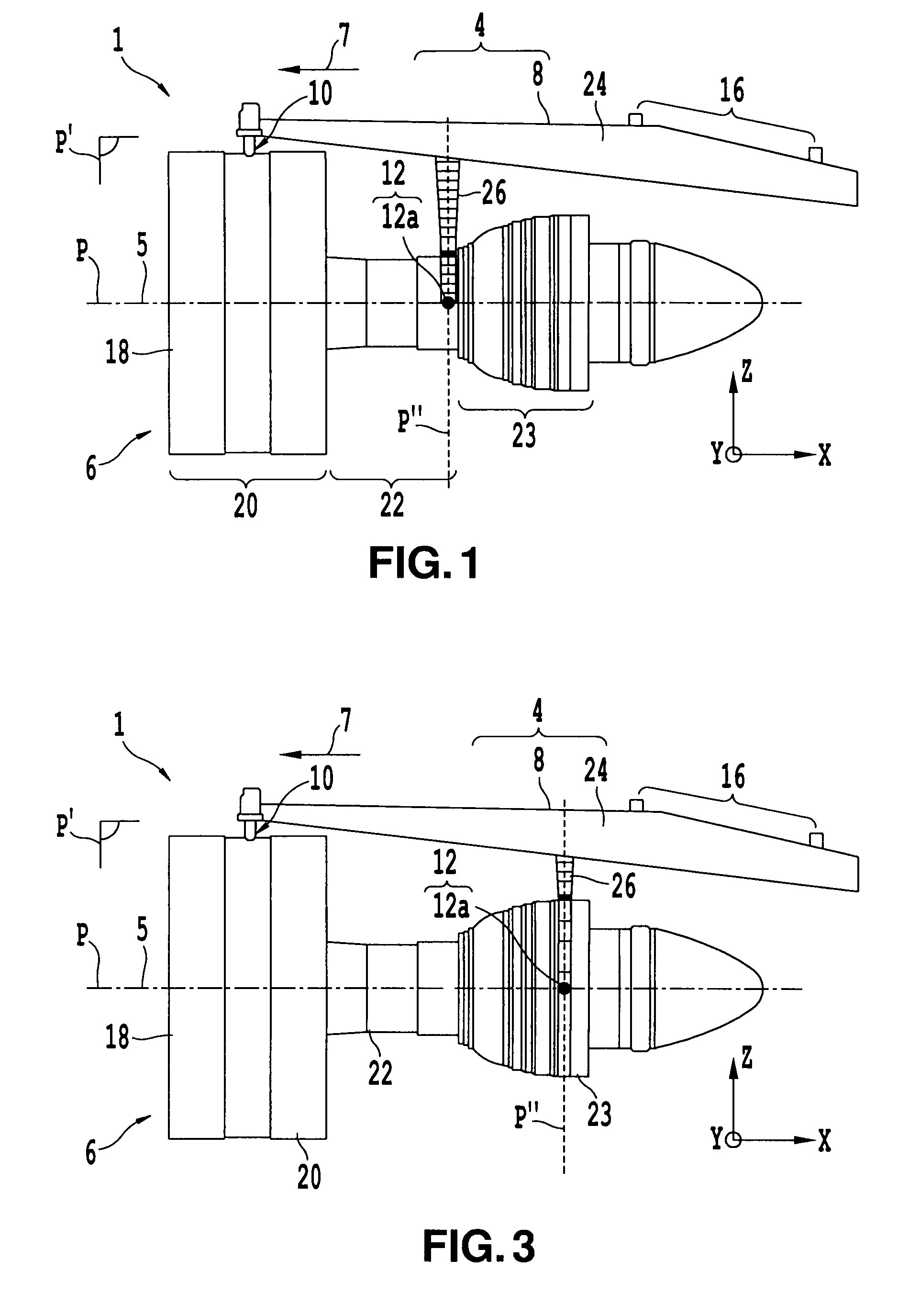
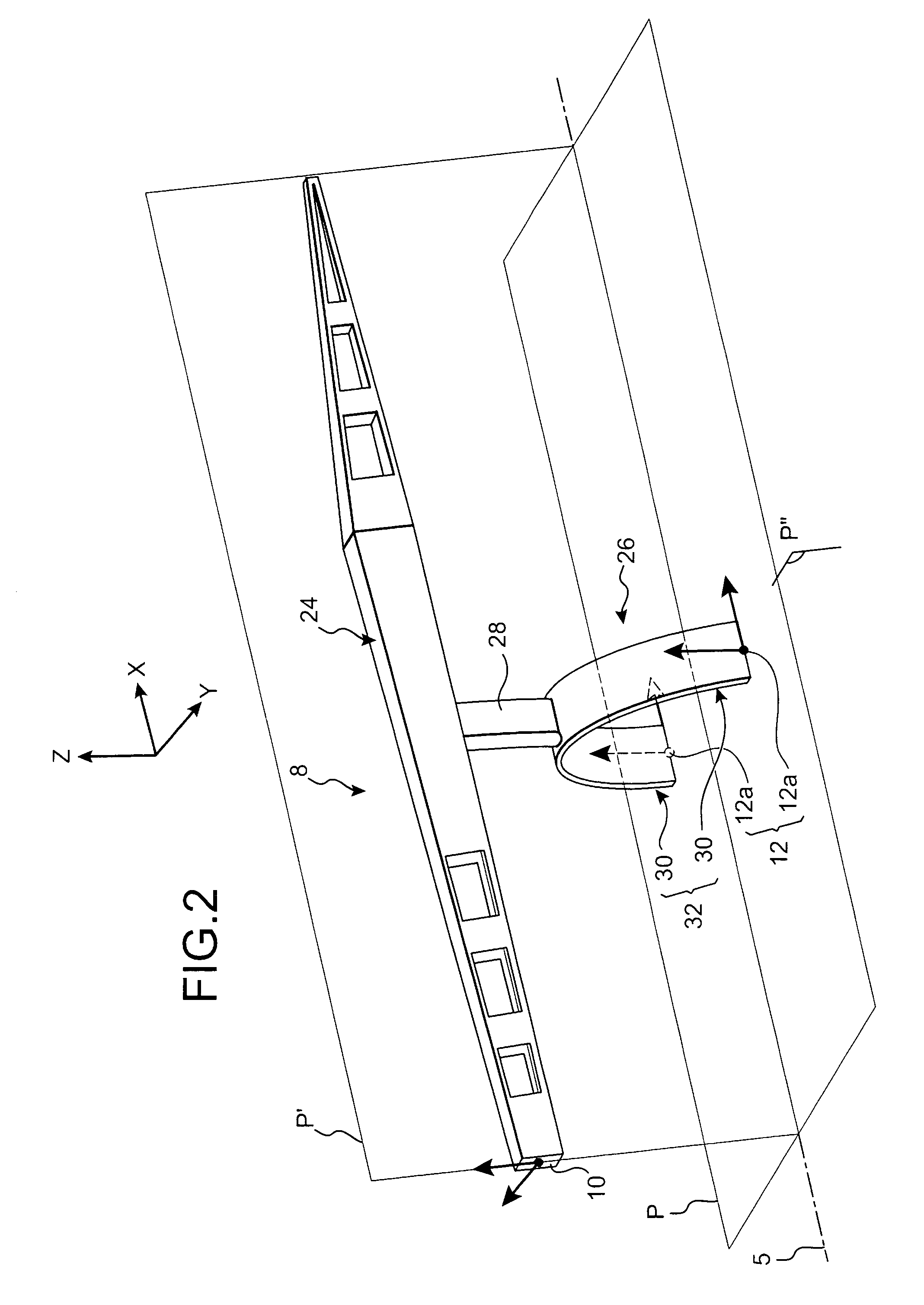
[0057]We will now refer to FIG. 3 showing an engine assembly 1 according to a second preferred embodiment of this invention, it can be seen that the only difference from the first embodiment shown in FIGS. 1 and 2 consists of positioning the fork 26 and the aft engine fastener 12 further in the aft direction, such that the two aft half-fasteners 12a are mounted fixed oh the ejection casing 23 of the engine 6, and preferably close to an aft end of this engine 6.

second embodiment

[0058]In this second embodiment in which the plane P″ in which the fork 26 is located is offset towards the aft direction, the horizontal plane passing through a longitudinal axis 5 of the engine 6 also naturally passes through the lower ends of the branches of the fork and the two aft half-fasteners 12a.

[0059]Obviously, various modifications can be made by those skilled in the art to the engine 1 assemblies for an aircraft that have just been described, solely as non-limitative examples.


PUM


Abstract

The invention relates to an aircraft engine assembly (1) including an engine (6) and an engine mounting device (4), the mounting device being designed to be inserted between a wing of the aircraft and the engine, and comprising a rigid structure (8) and means of mounting the engine onto the rigid structure, the mounting means comprising a forward fastener (10) and an aft fastener (12). According to the invention, the aft fastener comprises two aft half-fasteners (12a) that will each resist at least the forces applied along a longitudinal direction (X) of the engine, and the two aft half-fasteners are arranged so that a horizontal plane (P) passing through a longitudinal axis (5) of the engine passes through each of them.

Description

TECHNICAL DOMAIN[0001]This invention relates in general to the domain of mounting devices for engines that will be inserted between an aircraft wing and an engine, and more particularly an engine assembly comprising such a mounting device.[0002]The invention may be used on any aircraft type fitted with turbojets or turboprops, or any other type of engine.[0003]This type of mounting device, also called an Engine Mounting Structure (EMS) is used to suspend a turbo engine below the wing of an aircraft, or to mount this turbo engine above said wing.STATE OF PRIOR ART[0004]A mounting device of an aircraft is designed to form the connecting interface between an engine and a wing of the aircraft. It transmits forces generated by the associated engine to the aircraft structure, and it also enables routing of the fuel, electricity, hydraulics and air between the engine and the aircraft.[0005]In order to transmit forces, the pylon comprises a rigid structure, for example of the <<box>...

Claims


Application Information

Patent Timeline
Patent Type & Authority Patents(United States)
IPC IPC(8): B64D27/00
CPCB64D27/18B64D27/26
Inventor DIOCHON, LIONELEL HAMMAMI, SAMIRLE LOUVETEL-POILLY, JULIEDUMAS, JEAN-BAPTISTEKOENIG, NICOLAS
Owner AIRBUS OPERATIONS (SAS)
Why Eureka
Try Eureka